

Alloy cast iron and manufacturing method of rolling piston using the same
a manufacturing method and technology of alloy cast iron, which are applied in the direction of liquid fuel engines, furnaces, heat treatment apparatus, etc., can solve the problems of increased manufacturing costs, leakage of refrigerant, and abrasion of compressors for a long time, and achieves the effects of enhancing cutting function, reducing manufacturing costs, and ensuring the quality of the produ
- Summary
- Abstract
- Description
- Claims
- Application Information
AI Technical Summary
Benefits of technology
Problems solved by technology
Method used
Image

Examples
embodiment 1
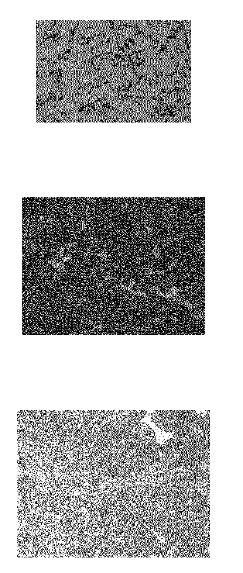
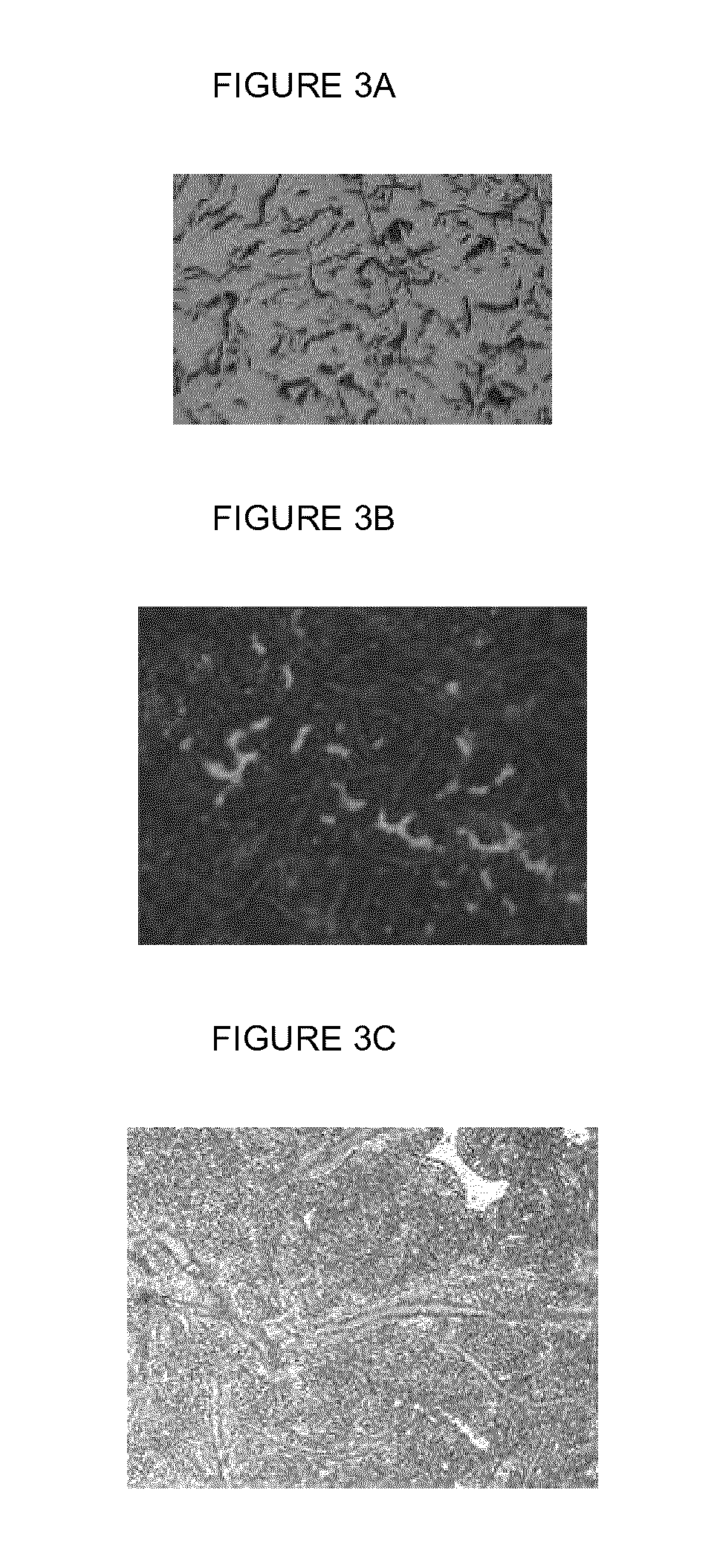
[0069]The hardness of the rolling piston after casting was high as 98 HRB. However, the hardness after the thermal processing was 49 HRC and the tensile strength was 293 MPa. Referring to FIG. 3A, graphite precipitated in the structure of the Embodiment 1 is about 80% A-type graphite in which flake graphite is smoothly curved and is uniformly distributed. Generally, A-type flake graphite is the most excellent among A˜E type graphite. Therefore, it can be seen that the rolling piston has an excellent physical property in the Embodiment 1.
[0070]Referring to FIG. 3B, it can be seen that the content of steadite is about 3%. Referring to FIG. 3C, it can be seen that the matrix structure of the Embodiment 1 is Martensite.
[0071]From the results, it can be seen that the rolling piston of the Embodiment 1 has the hardness and abrasion-resistance more excellent than those of the conventional rolling piston formed of alloy cast iron and having the hardness of 30˜40. Further, the rolling piston...
embodiment 2
[0072]The hardness after casting was high as 98 HRB. However, the hardness after the thermal processing was 50 HRC and the tensile strength was 298 MPa. Referring to FIG. 4A, graphite precipitated in the structure of the Embodiment 2 is about 90% A-type graphite in which flake graphite is smoothly curved and is uniformly distributed. Therefore, it can be seen that the rolling piston has also an excellent physical property in the Embodiment 2.
[0073]Referring to FIG. 4B, it can be seen that the content of steadite is about 3.5%. Referring to FIG. 4C, it can be seen that the matrix structure of the Embodiment 2 is Martensite.
[0074]It can be also seen that the rolling piston of the Embodiment 2 has the hardness and abrasion-resistance more excellent than those of the conventional rolling piston formed of alloy cast iron. Further, the rolling piston of the present invention has a similar function to a rolling piston containing Ni, Mo and Cr.
embodiment 3
[0075]The hardness after casting was high as 100 HRB. However, the hardness after the thermal processing was 51 HRC and the tensile strength was 300 MPa. Referring to FIG. 5A, graphite precipitated in the structure of the Embodiment 3 is about 95% A-type graphite in which flake graphite is smoothly curved and is uniformly distributed. Therefore, it can be seen that the rolling piston has also an excellent physical property in the Embodiment 3.
[0076]Referring to FIG. 5B, it can be seen that the content of steadite is about 4%. Referring to FIG. 5C, it can be seen that the matrix structure of the Embodiment 3 is Martensite.
[0077]It can be also seen that the rolling piston of the Embodiment 3 has the hardness and abrasion-resistance more excellent than those of the conventional rolling piston formed of alloy cast iron. Further, the rolling piston of the present invention has a similar function to a rolling piston containing Ni, Mo and Cr.
PUM
| Property | Measurement | Unit |
|---|---|---|
| Temperature | aaaaa | aaaaa |
| Temperature | aaaaa | aaaaa |
| Temperature | aaaaa | aaaaa |
Abstract
Description
Claims
Application Information