
Display device

a display device and component technology, applied in the field of display devices, can solve the problems of reducing the adhesion between the components of the display device, increasing the size of the product, and reducing the attractiveness of the product, so as to reduce the bezel area, remove or minimize the problem of dark portion

Active Publication Date: 2020-07-14
LG DISPLAY CO LTD
View PDF8 Cites 0 Cited by
  • Summary
  • Abstract
  • Description
  • Claims
  • Application Information

AI Technical Summary

Benefits of technology

The patent aims to address the issue of dark areas around the edges of display devices that have adhesive members. It also aims to minimize or remove the bezel area, which is the space around the display that is used to hold components and ensure proper functionality.

Problems solved by technology

A larger bezel area in which an image is not displayed may increase the size of the product and make the appearance of the product less attractive.
However, since the related art adhesive member is opaque and does not transmit light, the display device has a dark portion around its edges.
On the other hand, if the width of the adhesive member is reduced in order to minimize the bezel area, the adhesion between the components of the display device is weakened.

Method used


Image

  • Display device
  • Display device
  • Display device

Examples


Embodiment Construction

[0026]Reference will now be made in detail to embodiments of the present disclosure, examples of which may be illustrated in the accompanying drawings.

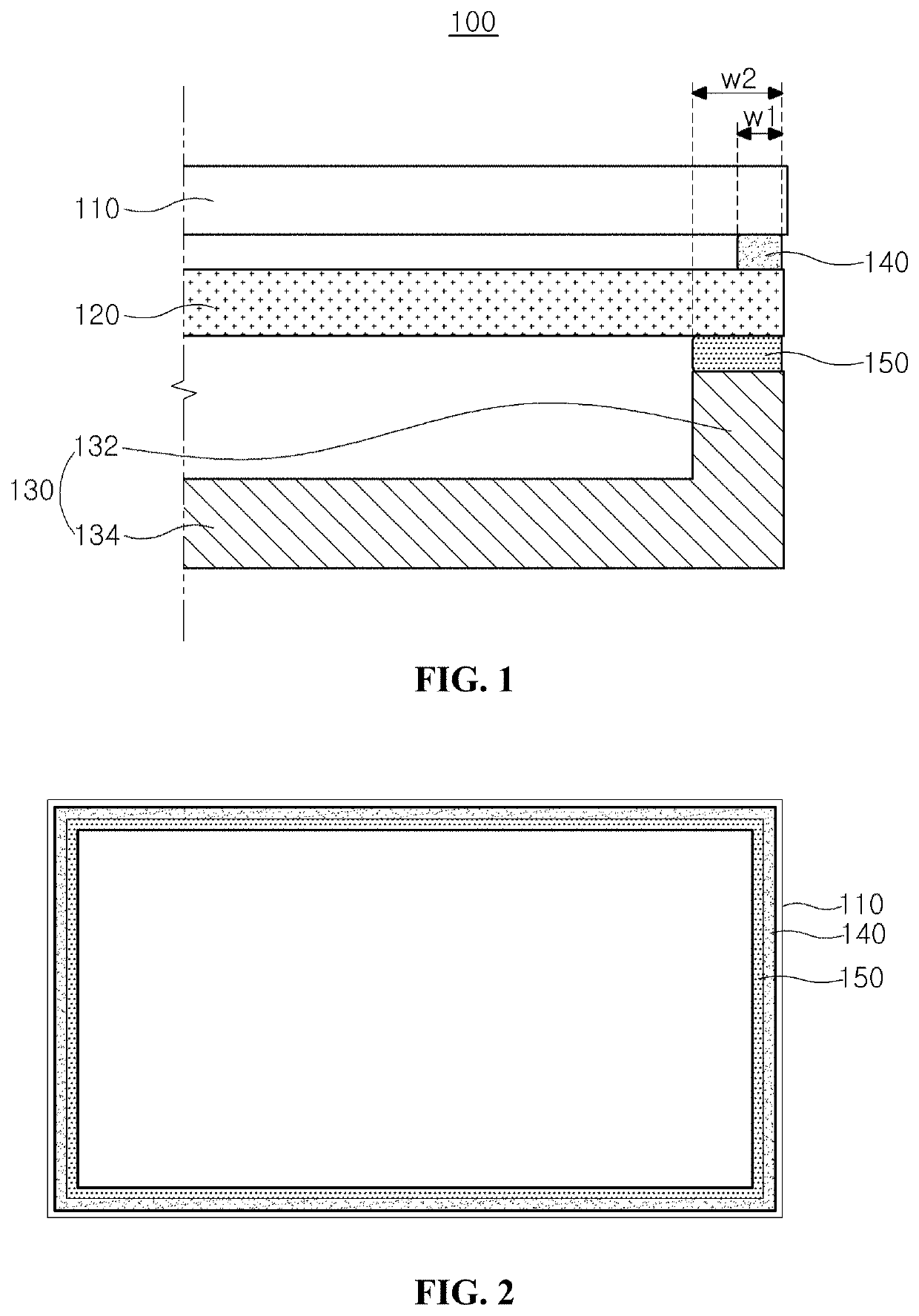
[0027]FIG. 1 is a cross-sectional view schematically showing a display device according to an embodiment of the present disclosure. FIG. 2 is a plan view schematically showing the display device according to an embodiment of the present disclosure.

[0028]As shown in FIG. 1 and FIG. 2, the display device 100 according to an embodiment of the present disclosure may include a display panel 110, an optical member 120, and a support member 130.

[0029]The display panel 110 may include a plurality of pixels and display an image through a front surface thereof. The display panel 110 may be a liquid crystal display panel including a liquid crystal capacitor or an electroluminescent display panel including a light-emitting diode, but the present disclosure is not limited thereto.

[0030]The optical member 120 may be disposed under the display panel...


PUM

PropertyMeasurementUnit
wavelength rangeaaaaaaaaaa
transmittanceaaaaaaaaaa
width w2aaaaaaaaaa

Abstract

A display device is disclosed. The display device includes a display panel configured to display an image, an optical member under the display panel, and a support member under the optical member. The display device further includes a first adhesive member between the display panel and the optical member, and a second adhesive member between the optical member and the support member. The first adhesive member has higher transmittance than the second adhesive member.

Description

CROSS-REFERENCE TO RELATED APPLICATION[0001]The present application claims priority from and the benefit of Korean Patent Application No. 10-2017-0097676 filed on Aug. 1, 2017, which is hereby incorporated by reference in its entirety for all purposes as if fully set forth herein.BACKGROUND OF THE INVENTION1. Technical Field[0002]The present disclosure relates to a display device, and more particularly, to a display device having no bezel area or a minimized bezel area using an adhesive member.2. Discussion of the Related Art[0003]With rapid development of information technologies, display devices for displaying a large amount of information are being developed. Recently, flat panel display (FPD) devices having a thin profile, light weight, and low power consumption, such as liquid crystal display devices or electroluminescent display devices, have been suggested and widely applied.[0004]The flat panel display devices are widely used for portable devices, such as smartphones, comput...

Claims


Application Information

Patent Timeline
Patent Type & Authority Patents(United States)
IPC IPC(8): G02F1/1333C09J4/00C09J11/08G02F1/13357C09J133/06C09J11/04C09J175/04C08G18/76G02F1/1368
CPCG02F1/133603C09J11/04G02F1/133606C09J11/08C09J4/00C09J175/04G02F1/133608C09J133/06G02F1/133308C08G18/7671G02F2001/133314G02F1/1368C09J2205/31G02F2203/03G02F2202/28G02F1/133504G09F9/30G09F9/35G02F1/133314G02F1/133605C09J2301/416
Inventor JO, TAE-SOO
Owner LG DISPLAY CO LTD
Learn More