System and method for enhancing bandwidth of low-dropout regulators using power transmission lines for high speed input output drivers

a technology of power transmission lines and regulators, which is applied in the direction of high frequency circuit adaptations, process and machine control, instruments, etc., can solve the problems of excessive power supply noise coupling from input, power supply rejection peaking, power supply noise passing through, etc., to enhance the effective noise-rejection bandwidth of ldo, reduce power supply noise, and increase energy efficiency

Active Publication Date: 2020-07-14
GEORGIA TECH RES CORP
View PDF3 Cites 0 Cited by
  • Summary
  • Abstract
  • Description
  • Claims
  • Application Information

AI Technical Summary

Benefits of technology

[0005]In an aspect, the invention is directed at a system and method that supplies power to I / O drivers efficiently with a reduction in power supply noise and an increase in energy efficiency as compared to the conventional power delivery method of using power and reference / ground planes. In an aspect, the I / O drivers can include high speed I / O drivers. In an aspect, the system utilizes setup found on SOCs to regulate the power to I / O drivers. In an aspect, the system includes a combination of a Voltage Regulator Module (VRM) with a Low Dropout (LDO) regulator connected in series with one another, for the LDO to deliver power to I / O drivers. In an aspect, the VRM and LDO can utilize a decoupling capacitor and a one dimensional Power Delivery Network (PDN). In an aspect, the PDN utilizes power transmission lines (PTL) instead of power planes to deliver power to I / O drivers. In such aspects, the PTL, in combination with a capacitor, both placed between the voltage regulator modules VRM and the LDO regulator, can be used to create a low impedance profile at the input of the LDO in the frequency band that the LDO's intrinsic power supply rejection (PSR) is deficient in rejecting noise so as to enhance the effective noise-rejection bandwidth of the LDO. Therefore, the LDO is able to deliver clean power to the power supply terminals of the I / O drivers while maintaining energy efficiency.
[0006]PTLs, unlike power / ground planes, are controlled-impedance structures that can be used for power delivery in electronic systems. The PTL can include a micro-strip, a strip line structure, or other types of impedance controlled transmission line structure. In an aspect, a micro-strip styled PTL can include a narrower thin power trace and a reference plane situated in an adjacent layer in the PCB or package substrate stackup. In such instances, the power trace is used to deliver current to the load while the reference plane serves as the current return path. In an aspect, PLTs reduce power supply noise for I / O drivers by eliminating return path discontinuities, minimizing coupling in mixed signal circuits, and significantly reducing the coupling between signal and power delivery networks in printed circuit boards.

Problems solved by technology

One limitation of the LDOs is the power supply rejection (PSR) peaking that occurs when its regulating feedback loop gain reaches 1 or 0 dB.
Around this frequency, the PSR of the LDO degrades, resulting in power supply noise passing through the LDO from its input to its output, which connects to the power supply nodes of I / O drivers or other types of loads through the power delivery network (PDN), without impediment.
Unfortunately, for typical LDOs, the PSR peaking occurs in the 50 MHz-100 MHz frequency range, in where the chip-package or board anti-resonances also occur.
A combination of ineffective noise rejection capability of the LDO due to PSR peaking and large package / board impedances can reduce the bandwidth of the LDO regulator leading to excessive power supply noise coupling from the input to the output of the LDO.
However, this method also implies more power is dissipated in the LDO by the high dropout voltage causing decreased LDO efficiency.

Method used


Image

  • System and method for enhancing bandwidth of low-dropout regulators using power transmission lines for high speed input output drivers
  • System and method for enhancing bandwidth of low-dropout regulators using power transmission lines for high speed input output drivers
  • System and method for enhancing bandwidth of low-dropout regulators using power transmission lines for high speed input output drivers

Examples


case 1

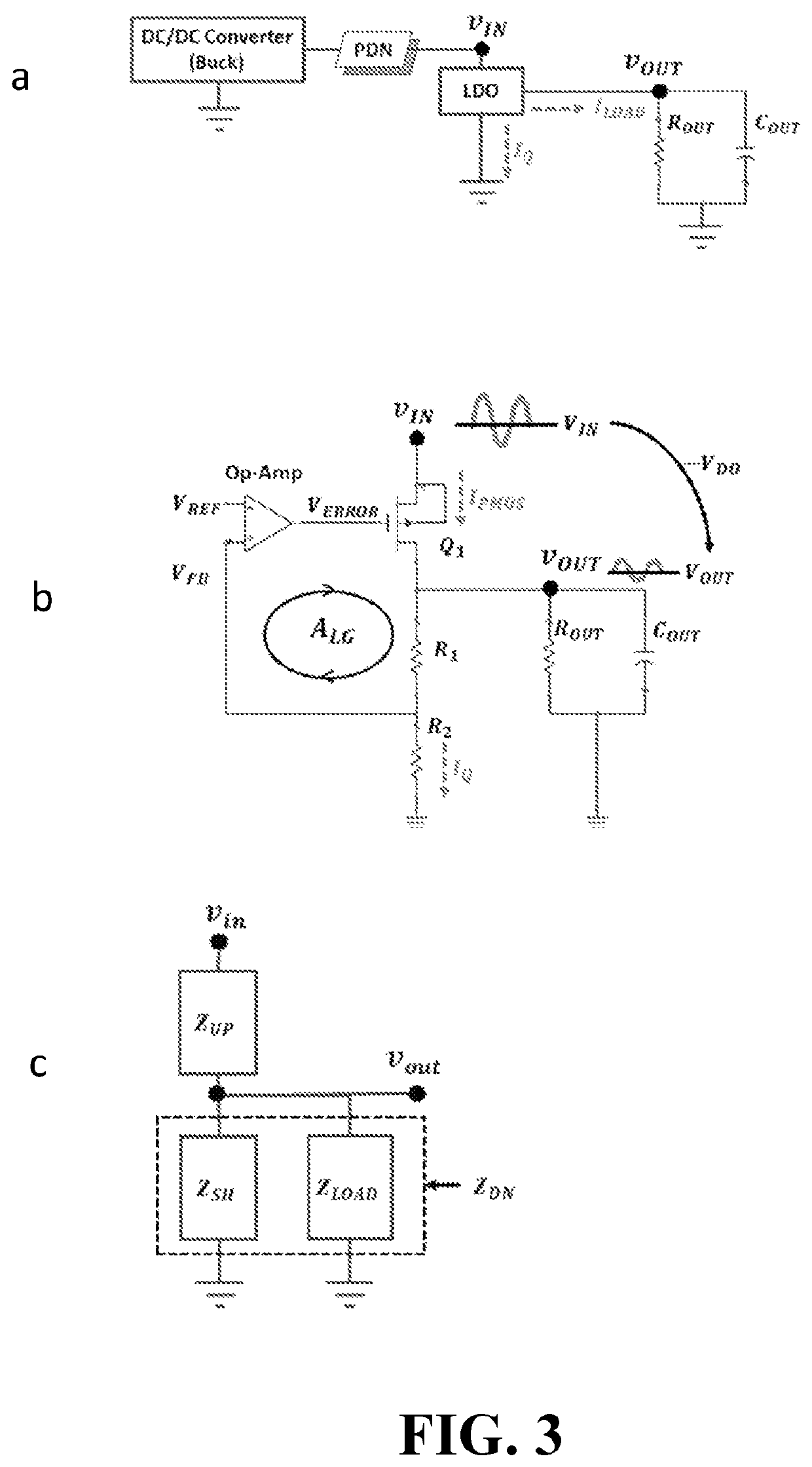
[0057] LDO Dropout Voltage, VDO=0.4V

[0058]In the first study, the dropout voltage across the LDO PMOS transistor was set as 0.4V. For ILOAD=0.1 A, the power absorbed by the PDN is PPDN=I2LOAD*RDC-plane=50 uW; the power loss due to the PMOS transistor is PDO=ILOAD*VDO=40 mW and output power is POUT=ILOAD*VOUT=80 mW. Therefore, the input power is 50 uW+40 mW+80 mW=120.05 mW according to:

PIN=(PPDN+PDO)+POUT=PLOSS+POUT  (9)

The energy conversion efficiency of the system is therefore:

[0059]ηSYS=POUTPIN=80120.5=66.6⁢%(10)

The LDO power supply noise at node VIN in FIG. 5 can be calculated as:

VINnoise=ZIN*Inoise  (11)

where Inoise is the noise current, which is assumed to be 5 mA, and ZIN is 99.45Ω from the simulation results. Based on the LDO circuit model discussed above, the PSR was calculated as −2.07 dB with a resulting power supply noise at the output of the LDO circuit to be ˜0.39V. The results of this case are shown in Table II below.

case 2

[0060] VDO=0.5V

[0061]In this study, the PSR of the LDO circuit was improved by increasing the dropout voltage to 0.5V. As can be seen in Table II, the PSR improves by 16.6% to −3.65 dB, which was obtained by setting VOUT=0.7V in the simulated LDO model. The resulting power supply noise at the output of the LDO circuit is ˜0.33V, which improved by 16.6% as compared to Case 1. However, due to the increased dropout across the PMOS transistor, the power efficiency reduces by 12.5% to 58.3% as compared to Case 1.

[0062]Hence, it is difficult to achieve high efficiency and low power supply noise at the output of the LDO circuit simultaneously, especially at frequencies where the PDN impedance peaks occur, as illustrated by the results in Table II. Utilizing a single dimension PDN like power transmission lines solves this problem, as described below.

Single Dimension Connector

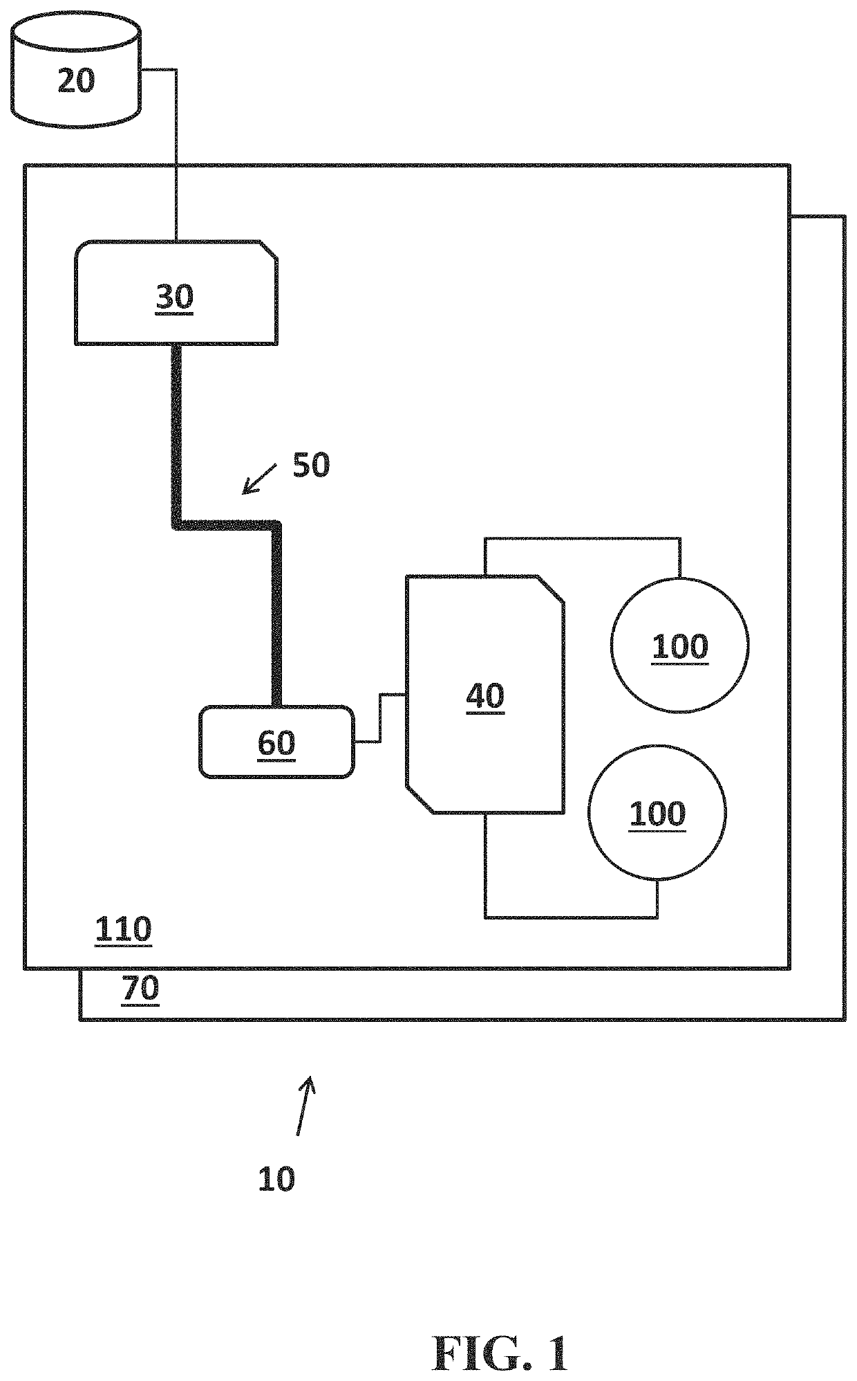
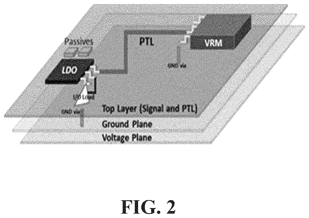
[0063]As shown in FIG. 2, the PDN for the I / O circuits is separated from the core, with the voltage and ground planes...

case 3

[0066] VDO=0.3V

[0067]In FIG. 7, the dropout voltage was set to 0.3V across the PMOS transistor resulting in a worsening of the PSR to −0.405 dB according to the simulated LDO model by setting VOUT=0.9V. However, since the self-impedance of the PDN, which is 1.68Ω, is much lower compared to the previous cases at around 50 MHz, the resulting power supply noise at the output of the LDO circuit is 8.04 mV, as represented by the significantly reduced noise power spike in B3 of FIG. 7 at the LDO out. As compared to Case 1, using a PTL reduces the power supply noise by 97.9%. Though the PTL has a higher simulated DC resistance (48.5 mΩ in this example), the overall energy conversion efficiency is 74.7%, an improvement of 12.1% as compared to Case 1 due to the lower dropout voltage. As can be seen from Table II, the results for Case 3 are much better as compared to both Cases 1 and 2 in terms of efficiency and power supply noise.

[0068]Therefore, co-designing the PTL with the LDO circuit lea...


PUM


Abstract

Power supply rejection (PSR) peaking in Low Dropout (LDO) voltage regulators can lead to reduced bandwidth and efficiency. The present invention is directed to a new design method by combining power transmission lines (PTL) with LDOs for enhancing its bandwidth and efficiency. This approach is applicable for LDOs regulating high speed I / O drivers. The PTL combined with decoupling capacitors on the package or board are used to mitigate the PSR peaking. This methodology is demonstrated using printed circuit board test vehicles with off-the-shelf components. When compared to conventional approaches, the PTL solution showed ˜80% lower power supply noise.

Description

BACKGROUND OF THE INVENTION[0001]Modem computer systems often include many voltage supplies. These are generated using DC / DC converters. A buck converter, a type of converter, can be used to step-down the voltage from a main DC supply. Depending on the voltage conversion ratio, buck converters, also referred to as Voltage Regulator Modules (VRM), have a power efficiency in the range of 70%-90%. To improve both power efficiency and voltage regulation, the recent trend is to move towards fully integrated voltage regulator (FIVR) modules to supply both the core and I / O circuits for System on Chip (SOC) applications. One implementation of a FIVR is to integrate the buck converter with SOC as a two chip solution on a package with passives such as inductors and capacitors either surface mounted or embedded in the package. Such two chip solutions can utilize a buck converter as the first chip and a Low Dropout regulator (LDO) as the second chip.[0002]To ensure fine grained power management...

Claims


Application Information

Patent Timeline
Patent Type & Authority Patents(United States)
IPC IPC(8): G05F1/575H05K1/02
CPCG05F1/575H05K1/0237H05K1/0243H05K1/025H05K1/0262
Inventor ZHANG, DAVID CHONGRAYCHOWDHURY, ARIJITSWAMINATHAN, MADHAVAN
Owner GEORGIA TECH RES CORP
Why Eureka
Try Eureka