
Surgical device with light

a surgical device and light technology, applied in the field of electrocautery devices having lighting components, can solve the problems of increasing the possibility of error, unable to specifically illuminate the targeted deep field site, and limited adjustment of overhead lighting

Active Publication Date: 2020-07-21
SURGIS CLEARVIEW LP
View PDF89 Cites 1 Cited by
  • Summary
  • Abstract
  • Description
  • Claims
  • Application Information

AI Technical Summary

Benefits of technology

The invention relates to an electrocautery unit that includes a body, a light unit, and an electrode. The electrode is connected at the distal end of the body and extends into the co-axis only at its tip. The light unit emits light that is coaxial to the body and the handle. The electrocautery kit includes a body with multiple connecting elements and an electrode that does not align with the body's central axis when connected. The invention also includes a pair of forceps with a light and camera units, and an electrocautery unit with a camera. The technical effects of the invention include improved visibility and precision during medical procedures using electrocautery tools.

Problems solved by technology

Both overhead lighting and headlamp approach provide sufficient ambient lighting during surgery, but often fail at specifically illuminating the targeted deep field site.
The adjustability of the overhead lighting is limited by its fixed position on the ceiling and its ability to be extended downward from the ceiling without hindering the surgeon's vision or movement.
Even with these extra movements, which increase the possibility of error, the bulk of the light from headlamps are blocked and / or reflected by the skin around the small incision and fails to penetrate the skin and illuminate the inside of the incision where the surgical procedure is taking place.
A lack of sufficient light at the treatment site within the patient's body may cause the doctor to accidentally injure other parts of the patient's body.

Method used


Image

  • Surgical device with light
  • Surgical device with light
  • Surgical device with light

Examples


Embodiment Construction

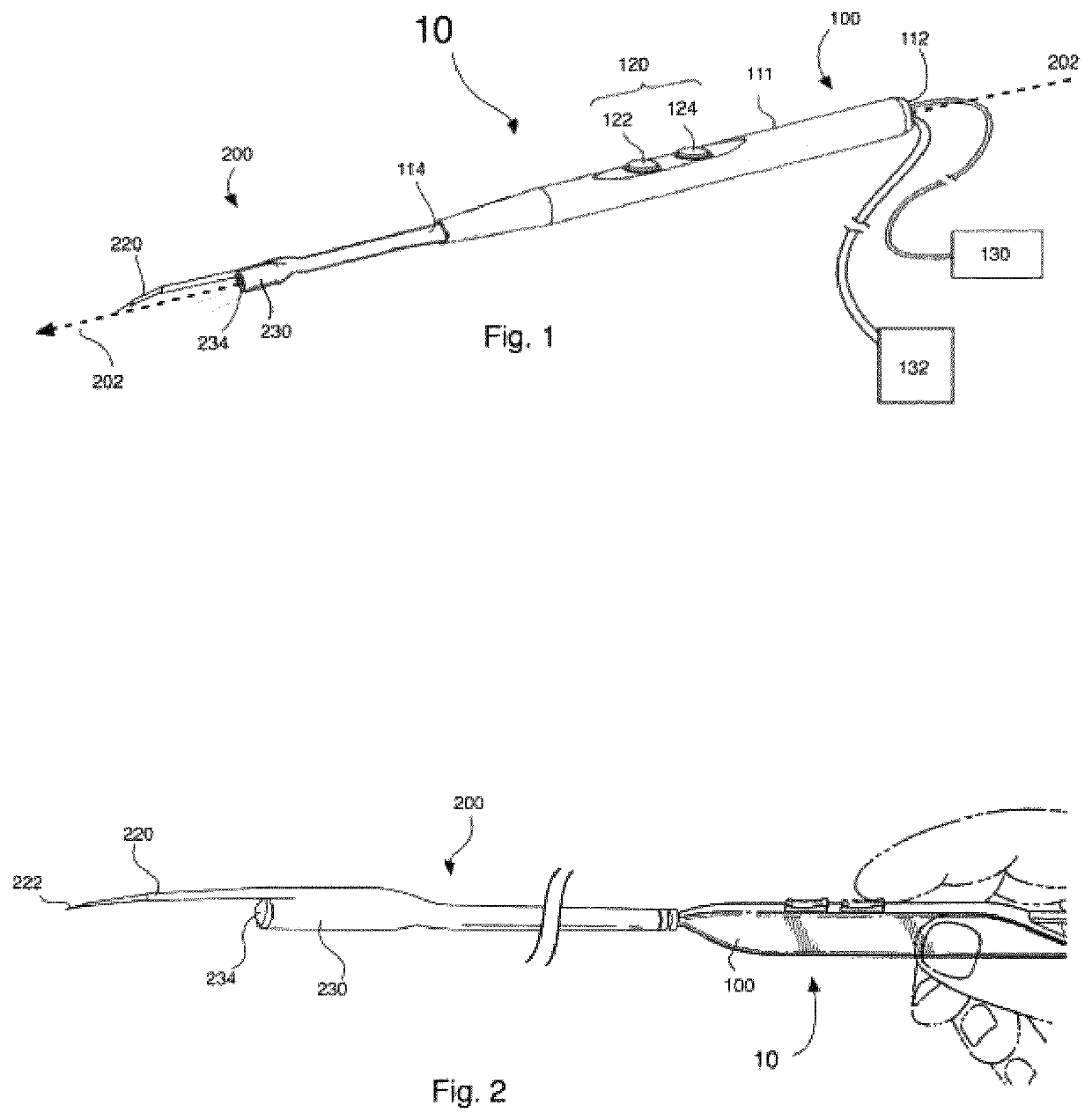
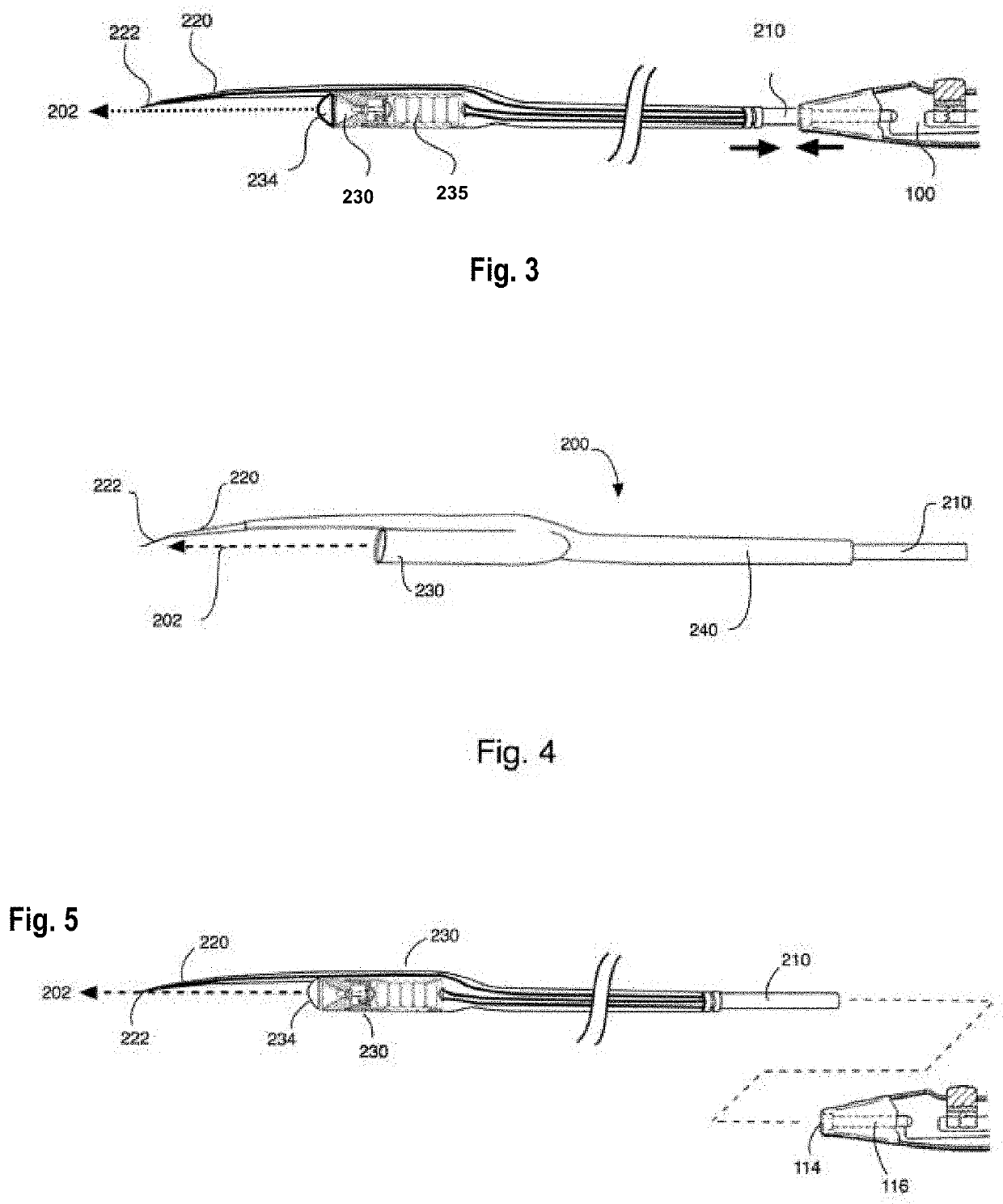
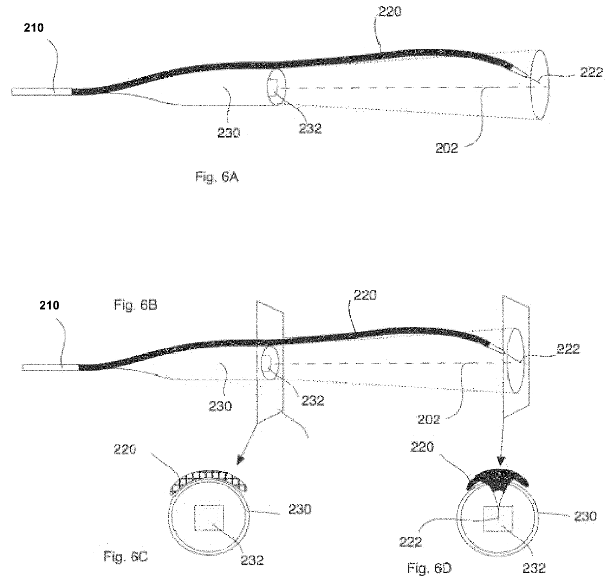
[0050]Certain exemplary embodiments of the present invention will now be described with reference to the drawings. Reference is made to FIGS. 1-16B, in which certain embodiments of the invention are shown. Generally, an electrocautery device 10 includes a handle 100 and a blade unit 200, 300, 400, 500 having a coupling element 210, 310, 410, 510 for removably connecting to handle 100, such that the same handle 100 may be used with a variety of blade units 200, 300, 400, 500. More preferably, handle 100 is a standard electrocautery handle, such that blade unit 200, 300, 400, 500 retrofits electrocautery handles currently available.

[0051]In the embodiments illustrated, coupling element 210, 310, 410, 510 includes a male connector constructed and arranged to be inserted into handle 100. However, it is to be understood that the coupling element may include a female receiving portion for receiving a male connector of the handle, or other coupling mechanisms, such as a threated mechanism,...


PUM


Abstract

An electrocautery unit for connecting to a handle of an electrocautery device, the unit comprises a body, a light unit and an electrode. The body has a body proximal end and a body distal end, and a body axis extending lengthwise along the center of the body. The body's proximal end comprises a connecting element for connecting said body to a handle having a handle axis extending lengthwise along the center of the handle, so that said body axis is coaxial with said handle axis when said body is connected to said handle. The light unit may be constructed and arranged to emit a light having a central axis coaxial with said body axis. The electrode comprises a proximate end connected to the body distal end, and an electrode tip at a distal said. When the electrode is connected to the body, the electrode lays outside of the body axis and extends into said body axis such that the electrode tip is within said body axis, wherein said light and said electrode tip are coaxial to said body axis and said handle axis.

Description

CROSS REFERENCE TO RELATED APPLICATION[0001]The application claims the benefit of U.S. Provisional Application No. 62 / 012,216 titled “A Surgical Lighting Hand-Piece Device with Electrocautery and Video Capabilities,” filed Jun. 13, 2014, which is incorporated by reference herein in its entirety.FIELD OF INVENTION[0002]The present invention is related generally to a medical apparatus and an electrocautery system and particularly to electrocautery tools having a lighting component to provide light during deep surgical procedures.BACKGROUND OF THE INVENTION[0003]Proper lighting is a critical component of any operating room. Surgeons need ample lighting to illuminate the area on which the procedure is taking place. Modern surgery has evolved continuously to smaller opening incisions and more complex operating sites, all with the objective of leaving smaller scars and creating less discomfort for the patient. For example, in cosmetic surgery, among others, there is a need to perform bett...

Claims


Application Information

Patent Timeline
Patent Type & Authority Patents(United States)
IPC IPC(8): A61B17/28A61B90/30A61B90/00A61B18/14
CPCA61B17/2812A61B90/30A61B18/14A61B2018/1462A61B2218/007A61B18/1477A61B2018/1407A61B2018/1412A61B90/361A61B2090/309A61B18/148
Inventor ALBERTAL, JORGE MANUEL
Owner SURGIS CLEARVIEW LP
Learn More