Powering a bipolar electrocautery surgical instrument

a surgical instrument and power cable technology, applied in the field of powering a bipolar electrocautery surgical instrument, can solve the problems of affecting the operation efficiency of the power cable of the electrocautery instrument, and putting a lot of strain on the power cabl

Pending Publication Date: 2020-05-07
CMR SURGICAL LTD
View PDF0 Cites 0 Cited by
  • Summary
  • Abstract
  • Description
  • Claims
  • Application Information

AI Technical Summary

Benefits of technology

The invention is a robotic surgical instrument with a unique articulation system that allows for the rotation of the electrocautery end effector. The articulation system includes a first joint and a second joint, which allow for rotation about a first axis and a second axis, respectively. The electrocautery end effector is powered by two electrocautery elements, which are connected to a shaft through the articulation system. The instrument also includes a pulley arrangement with two pairs of driving elements that are constrained to move around the pulleys. The driving elements and electrocautery elements are designed to resist compression and tension forces. The technical effects of this invention include improved precision and control during robotic surgery procedures.

Problems solved by technology

The mechanism described in US 2004 / 0267254 for managing the power cable of the electrocautery instrument is not effective for an instrument having a smaller external diameter, for example of less than 6 mm.
This is because accommodating the power cable through changes in its wound radii in a chamber put too much strain on the power cable.

Method used


Image

  • Powering a bipolar electrocautery surgical instrument
  • Powering a bipolar electrocautery surgical instrument
  • Powering a bipolar electrocautery surgical instrument

Examples


Embodiment Construction

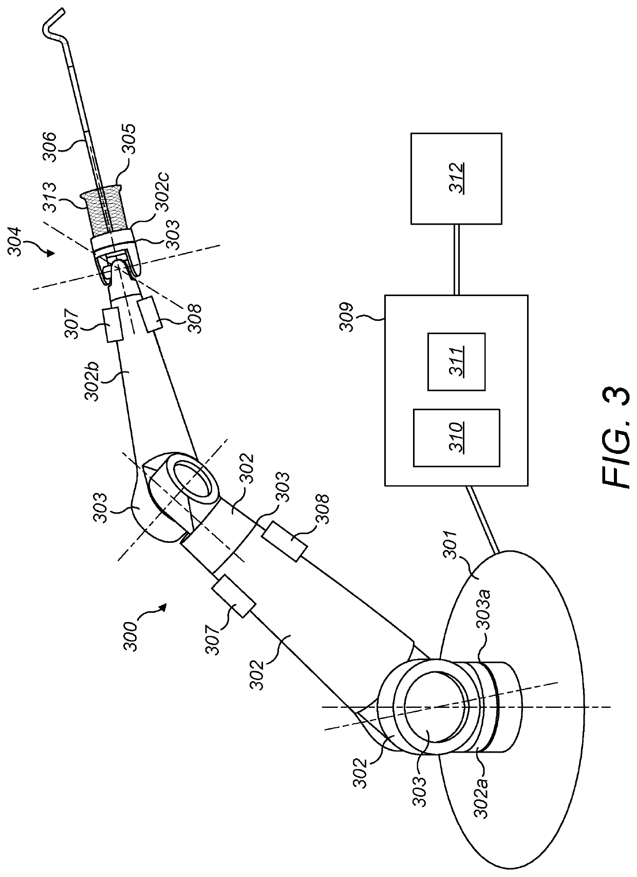
[0035]FIG. 3 illustrates a surgical robot having an arm 300 which extends from a base 301. The arm comprises a number of rigid limbs 302. The limbs are coupled by revolute joints 303. The most proximal limb 302a is coupled to the base by joint 303a. It and the other limbs are coupled in series by further ones of the joints 303. Suitably, a wrist 304 is made up of four individual revolute joints. The wrist 304 couples one limb (302b) to the most distal limb (302c) of the arm. The most distal limb 302c carries an attachment 305 for a surgical electrocautery instrument 306. Each joint 303 of the arm has one or more motors 307 which can be operated to cause rotational motion at the respective joint, and one or more position and / or torque sensors 308 which provide information regarding the current configuration and / or load at that joint. Suitably, the motors are arranged proximally of the joints whose motion they drive, so as to improve weight distribution. For clarity, only some of the ...


PUM


Abstract

A robotic surgical instrument comprising a shaft, an electrocautery end effector powered by a first electrocautery element and a second electrocautery element, and an articulation. The articulation connects the electrocautery end effector to the shaft, and comprises a first joint driveable by a first pair of driving elements, the first joint permitting the electrocautery end effector to rotate about a first axis transverse to a longitudinal axis of the shaft. The first joint comprises a pulley arrangement around which the first pair of driving elements and the first and second electrocautery elements are constrained to move, the first and second electrocautery elements having symmetrically opposing paths around the pulley arrangement. The first and second electrocautery elements are distinct from the first pair of driving elements.

Description

BACKGROUND[0001]It is known to use robots for assisting and performing surgery. FIG. 1 illustrates a typical surgical robot 100 which consists of a base 108, an arm 102, and an instrument 105. The base supports the robot, and is itself attached rigidly to, for example, the operating theatre floor, the operating theatre ceiling or a trolley. The arm extends between the base and the instrument. The arm is articulated by means of multiple flexible joints 103 along its length, which are used to locate the surgical instrument in a desired location relative to the patient. The surgical instrument is attached to the distal end 104 of the robot arm. The surgical instrument penetrates the body of the patient 101 at a port 107 so as to access the surgical site. At its distal end, the instrument comprises an end effector 106 for engaging in a medical procedure.[0002]A variety of end effectors are known, each adapted to perform a particular surgical function. FIG. 2 illustrates a surgical instr...

Claims


Application Information

Patent Timeline
IPC IPC(8): A61B18/14A61B34/37
CPCA61B2034/742A61B2018/126A61B34/37A61B2017/00327A61B2034/305A61B2018/1422A61B2018/1253A61B2018/00601A61B2034/302A61B18/1445A61B2018/146A61B2018/00595A61B2018/00589A61B2018/144A61B2018/1457A61B34/71A61B34/30A61B2034/715B25J17/0241B25J17/025A61B2034/306
Inventor GROVER, SIMON RODERICK
Owner CMR SURGICAL LTD
Why Eureka
Try Eureka