Specialized robot motion planning hardware and methods of making and using same

a technology of motion planning and robots, applied in the field of specialized robot motion planning hardware and methods of making and using same, can solve the problems of insufficient speed for real-time motion planning, large number of collision checks, and computational intensive motion planning algorithms, and achieve the effect of low cos

Active Publication Date: 2020-07-28
DUKE UNIV
View PDF63 Cites 11 Cited by
  • Summary
  • Abstract
  • Description
  • Claims
  • Application Information

AI Technical Summary

Benefits of technology

[0005]Specialized robot motion planning hardware and methods of making and using same are provided. The described hardware can address the challenge of real-time motion planning. The described systems and methods can take a specific robot and produce a low-power, low-cost hardware architecture capable of performing real-time motion planning for that robot.

Problems solved by technology

In many situations, a major constraint on the usefulness of robots is their ability to perform real-time motion planning in environments with obstacles.
Motion planning algorithms tend to be computationally intensive, requiring a vast number of collision checks for each movement.
However, running collision detection software on general-purpose processors is insufficiently fast for real-time motion planning and / or is too power-hungry (if using GPUs) for many target applications.

Method used


Image

  • Specialized robot motion planning hardware and methods of making and using same
  • Specialized robot motion planning hardware and methods of making and using same
  • Specialized robot motion planning hardware and methods of making and using same

Examples


example implementation

[0068]A motion planning processor was designed for a 6-degree JACO-2 arm from Kinova. The sensor system for the robot involves multiple Kinect-2 modules to enable a visualization of the environment. For the example implementation, a motion planning processor was designed specifically for the control of the arm and connected to the robot through an I / O port of the robot. The Robot Operating System (ROS) software ecosystem, available from the Open Source Robotics Foundation, was used for controlling the robot and interfacing to the motion planning processor. The ROS ecosystem is used to interpret objects in the environment from the output of the Kinect-2 modules and the representations generated by the ROS software running on the robot are communicated to the motion planning processor.

[0069]With local and / or global optimization (such as described with respect to FIG. 4), it was found that on the order of 5000 collision detection units were possible to fit on a high capacity FPGA. In a...

example alternative implementation

[0070]For a mesh model / triangle implementation, since each triangle has three vertices, each vertex can be described with its 3D coordinates.

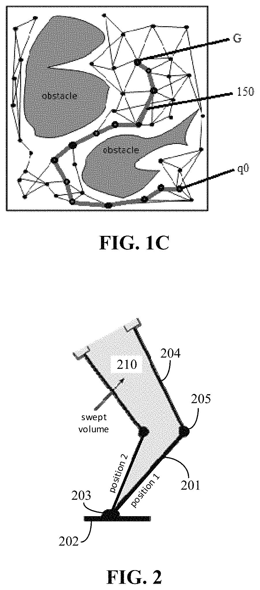
[0071]In a case where collision detection units include circuitry for computing triangle collisions, a robot can stream object triangles to the motion planning hardware and collision detection units configured to detect whether robotic movements would cause collisions with these object triangles. In this example implementation, each collision detection unit is responsible for one edge in the graph, which represents one possible robot movement. The robot movement corresponds to a volume in 3D-space that is swept in the course of performing that movement. Here, the collision detection unit can represent the swept volume as a hull consisting of triangles and can store nine k-bit numbers for each triangle. Then, to detect collisions with an incoming object triangle, the collision detection unit performs several computations to determine whether tri...


PUM


Abstract

Specialized robot motion planning hardware and methods of making and using same are provided. A robot-specific hardware can be designed using a tool that receives a robot description comprising a collision geometry of a robot, degrees of freedom for each joint of the robot, and joint limits of the robot; receives a scenario description; generates a probabilistic roadmap (PRM) using the robot description and the scenario description; and for each edge of PRM, produces a collision detection unit comprising a circuit indicating all parts of obstacles that collide with that edge. The hardware is implemented as parallel collision detection units that provide collision detection results used to remove edges from the PRM that is searched to find a path to a goal position.

Description

CROSS-REFERENCE TO RELATED APPLICATIONS[0001]The present application is the U.S. National Stage Application of International Application No. PCT / US16 / 12204, filed Jan. 5, 2016, which claims the benefit of U.S. Provisional Application Ser. No. 62 / 107,755, filed Jan. 26, 2015, which are hereby incorporated by reference their entirety, including any figures, tables, and drawings.BACKGROUND[0002]Many of the most exciting applications of computing today are in robotics. Recent advances in robotics have greatly expanded the opportunities for robots to change the way people live. Robots are being developed for a wide spectrum of real-world applications including health care, personal assistance, general-purpose manufacturing, search-and-rescue, and military operations. Unlike traditional robotics applications in which a robot operates in a tightly controlled environment (e.g., on an assembly line where the environment is static and known a priori), these applications require the robot to p...

Claims


Application Information

Patent Timeline
Patent Type & Authority Patents(United States)
IPC IPC(8): B25J9/16G06N7/00
CPCB25J9/1666G06N7/005G05B2219/40429Y10S901/49G05B2219/40476Y10S901/02G05B2219/40317G05B2219/40448G05B2219/40446G06N7/01
Inventor KONIDARIS, GEORGE D.SORIN, DANIEL J.
Owner DUKE UNIV
Why Eureka
Try Eureka