
Pressure medium unit, in particular for setting and/or regulating a brake pressure in a vehicle brake system having electronic slip regulation, and cap-shaped filter element

a technology of pressure medium unit and brake pressure, which is applied in the direction of fluid pressure control, separation process, instruments, etc., can solve problems such as undesirable leakag

Active Publication Date: 2020-08-11
ROBERT BOSCH GMBH
View PDF4 Cites 0 Cited by
  • Summary
  • Abstract
  • Description
  • Claims
  • Application Information

AI Technical Summary

Benefits of technology

[0009]A pressure medium unit having the features described herein has, in contrast, the advantage that a radial and / or axial play that occurs at the filter element when there are changes in temperature is compensated or prevented. The arising of a hydraulic bypass around the filter element is avoided, and pressure medium-controlling components that are situated downstream from the filter element in the pressure medium circuit are protected more reliably against potential damage or leaks caused by contamination.
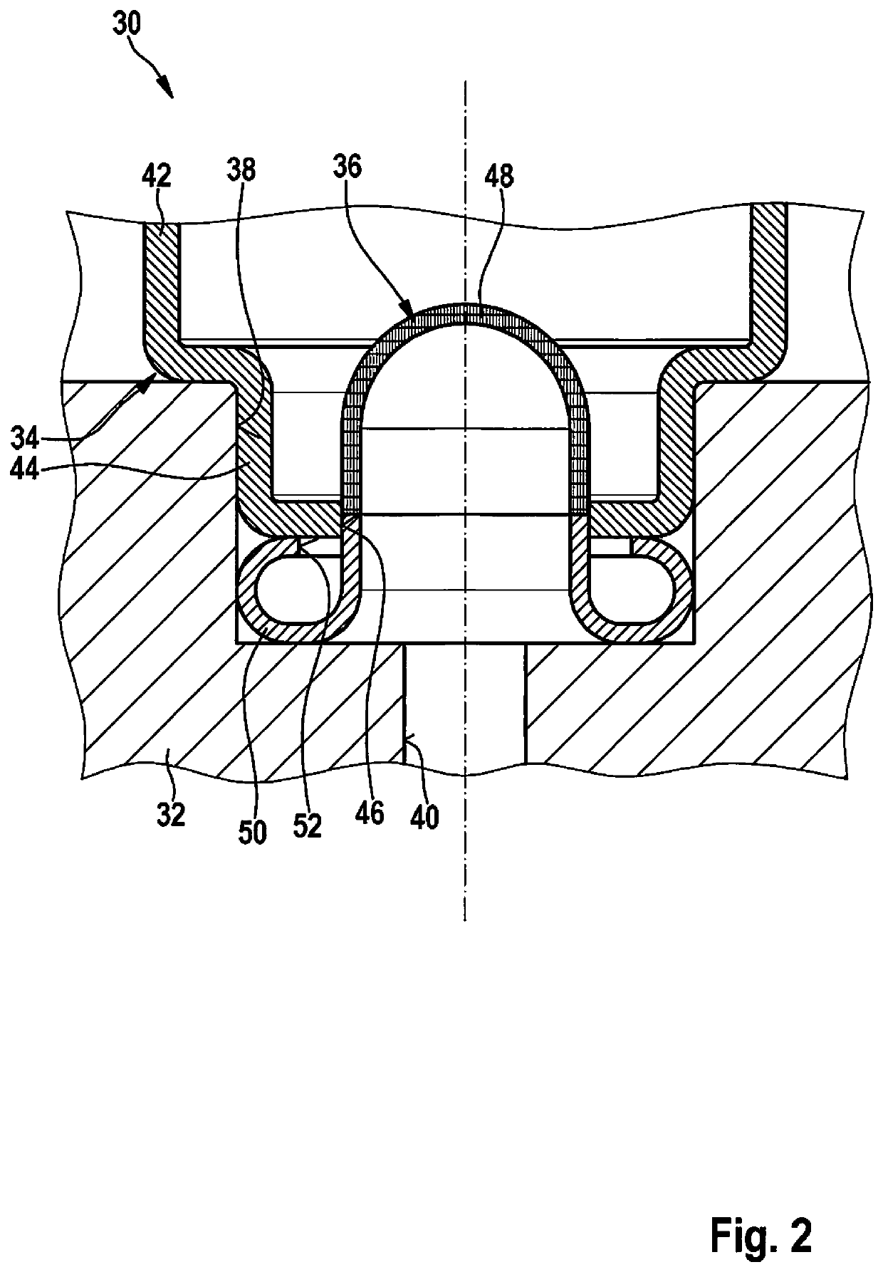
[0012]The fixing segment according to the present invention forms a hollow element having an annular gap running along the outer circumference of the filter body. A filter element having such a fixing segment may be made in one piece of metal. On the one hand, this reduces differences in expansion, caused by changes in temperature, between the filter element and the surrounding components, and on the other hand it simplifies the process of producing the filter element. In addition, the filter element and control valve together form an assembly that can be pre-assembled, having compact dimensions in the axial direction, and which can be anchored on the housing block in a single work step. An undesired deformation that may occur during assembly of the pressure medium unit, or damage to the filter mesh of the filter element, and consequently a worsening of the flow resistance of the filter element under operating conditions, is largely excluded by a filter element formed in accordance with the present invention. The lower support forces in the radial and axial direction of the proposed filter element also contribute to this. In addition, lower support forces are associated with lower assembly forces, and thus fewer potential risks of creating chips or shavings when a control valve is assembled to the housing block.

Problems solved by technology

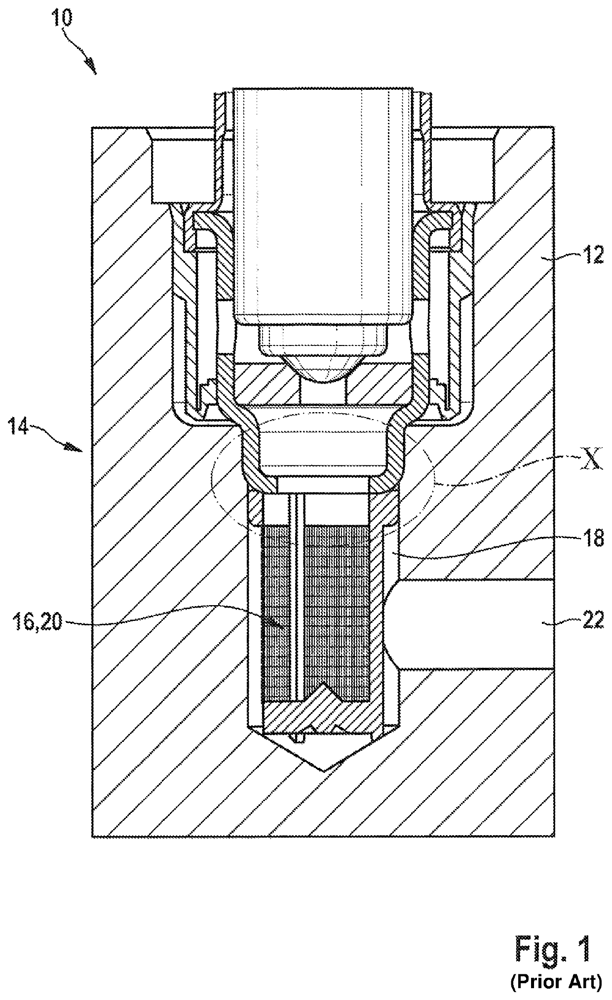
Contaminants that may be present in the pressure medium can cause damage to the components that control the pressure medium, in particular the control valves, and can result in undesirable leaks.

Method used


Image

  • Pressure medium unit, in particular for setting and/or regulating a brake pressure in a vehicle brake system having electronic slip regulation, and cap-shaped filter element
  • Pressure medium unit, in particular for setting and/or regulating a brake pressure in a vehicle brake system having electronic slip regulation, and cap-shaped filter element

Examples


Embodiment Construction

[0016]In FIG. 2, a pressure medium unit 30 is shown that is made up of a housing block 32, a control valve 34 anchored on housing block 32, and a filter element 36 configured according to the present invention. A receptacle 38 for control valve 34 is configured on housing block 32. This is a blind hole-type bore that opens at an outer side of housing block 32, and whose base is situated in the interior of housing block 32. The transition from a bore wall surrounding the bore to the base of the bore is formed as a right angle. The named receptacle is connected to a circuit (not further shown) that conducts pressure medium via a duct 40 that opens at the base of the bore.

[0017]As stated, control valve 34 is set into receptacle 38, but in the Figure only a valve housing 42, defining an outer contour of the control valve, is shown. This valve housing 42 has a hollow cylindrical shape whose outer diameter has one right-angled constriction. At the point of the reduction in diameter, valve...


PUM

PropertyMeasurementUnit
pressureaaaaaaaaaa
flow rateaaaaaaaaaa
axial pre-tensionaaaaaaaaaa

Abstract

A pressure medium unit, in particular for setting and / or regulating a brake pressure in a vehicle brake system having electronic slip regulation, and to a cap-shaped filter element. Pressure medium units are equipped with a housing block having a duct formed therein that conducts pressure medium, a control element that controls a cross-section of the duct, and a filter element assigned to the control element and fixed in the interior of the duct. According to the present system, the filter element is formed in the shape of a cap, and has on its outer circumference a radially protruding fixing segment having an elastically deformable cross-section. A fixing segment realized in this manner compensates differences in expansion between the components caused by changes in temperature, prevents play at the filter element, and provides a particularly good filter effect.

Description

RELATED APPLICATION INFORMATION[0001]The present application claims priority to and the benefit of German patent application no. 10 2017 213 885.8, which was filed in Germany on Aug. 9, 2017, the disclosure which is incorporated herein by reference.FIELD OF THE INVENTION[0002]The present invention relates to a pressure medium unit, in particular for setting and / or regulating a brake pressure in a vehicle brake system having electronic slip regulation, and to a cap-shaped element.BACKGROUND INFORMATION[0003]In the following, vehicle brake systems having slip regulation are understood as hydraulic brake systems having anti-lock protection (ABS), anti-slip regulation (ASR), and / or driving dynamics regulation (ESP), in which the brake pressure of the wheel brakes is set as a function of the slippage conditions at each of the associated wheels. This pressure adaptation can be carried out automatically, i.e. without driver involvement, or with involvement of the driver. The pressure mediu...

Claims


Application Information

Patent Timeline
Patent Type & Authority Patents(United States)
IPC IPC(8): B01D46/24B01D39/10B01D29/15G05D16/20B60T15/36B60T17/22B01D35/02B01D35/26B60T8/17B60T8/00B60T8/36
CPCB60T8/3615G05D16/2013B01D39/10B60T8/17B60T8/00B01D29/15B60T17/221B01D46/2414B01D35/26B01D35/02B60T15/36G05D16/2066B60T2270/203B60T2270/10B60T8/363B01D2201/347Y10T137/8085B60T2270/306B01D2201/16B60T8/3675B01D2201/40Y10T137/794Y10T137/8122B01D29/11B60T17/02
Inventor SCHUBITSCHEW, VALENTINGARDT, ANDREJEDELMANN, VOLKER
Owner ROBERT BOSCH GMBH
Learn More