Lubricating system of vehicle transmission device

a technology of transmission device and lubricating system, which is applied in the direction of gearing details, belt/chain/gearing, gear lubrication/cooling, etc., can solve the problems of insufficient lubrication of gear mechanism and bearing, low level of first oil storage part, and inability to supply lubricating oil to the first, so as to achieve stable maintenance and reduce the oil level of the first oil storage part.

Active Publication Date: 2020-08-11
TOYOTA JIDOSHA KK
View PDF26 Cites 2 Cited by
  • Summary
  • Abstract
  • Description
  • Claims
  • Application Information

AI Technical Summary

Benefits of technology

[0007]In view of the above circumstances, the present disclosure provides a lubricating system of a vehicle transmission device that includes a third oil storage part having a first outlet that allows lubricating oil to flow out by gravity toward a first oil storage part without passing through a second oil storage part, and that can thereby stably maintain the oil level in the first oil storage part.
[0027]According to this lubricating system, the third oil storage part includes the second outlet that allows the lubricating oil to flow out by gravity toward the second oil storage part when the amount of lubricating oil stored in the third oil storage part is less than or equal to the predetermined amount. Thus, the lubricating oil returns by gravity from the second outlet to the second oil storage part when the oil level in the first oil storage part is not significantly low, so that a significant decrease in the oil level in the first oil storage part can be avoided as well as the oil level in the second oil storage part can be stably maintained.

Problems solved by technology

However, in the case of a vehicle such as an electric vehicle or a hybrid electric vehicle that supplies lubricating oil stored in a first oil storage part to a gear mechanism and a bearing by a mechanical oil pump and that supplies lubricating oil stored in a second oil storage part to a driving motor by a mechanical or electrical oil pump, the lubricating systems of the above patents that control the oil level in the first oil storage part by supplying the lubricating oil stored in the second oil storage part or the catch tank to the first oil storage part may fail to supply the lubricating oil to the first oil storage part when the oil level in the second oil storage part or the catch tank is low.
As a result, the oil level in the first oil storage part may become significantly low, making it impossible to sufficiently lubricate the gear mechanism and the bearing.
However, it is difficult to design a valve that functions stably under temperature conditions from low temperature to room temperature in a lubricating system that includes a so-called dry sump structure with a pump configuration having a low circuit pressure.

Method used


Image

  • Lubricating system of vehicle transmission device
  • Lubricating system of vehicle transmission device
  • Lubricating system of vehicle transmission device

Examples


first embodiment

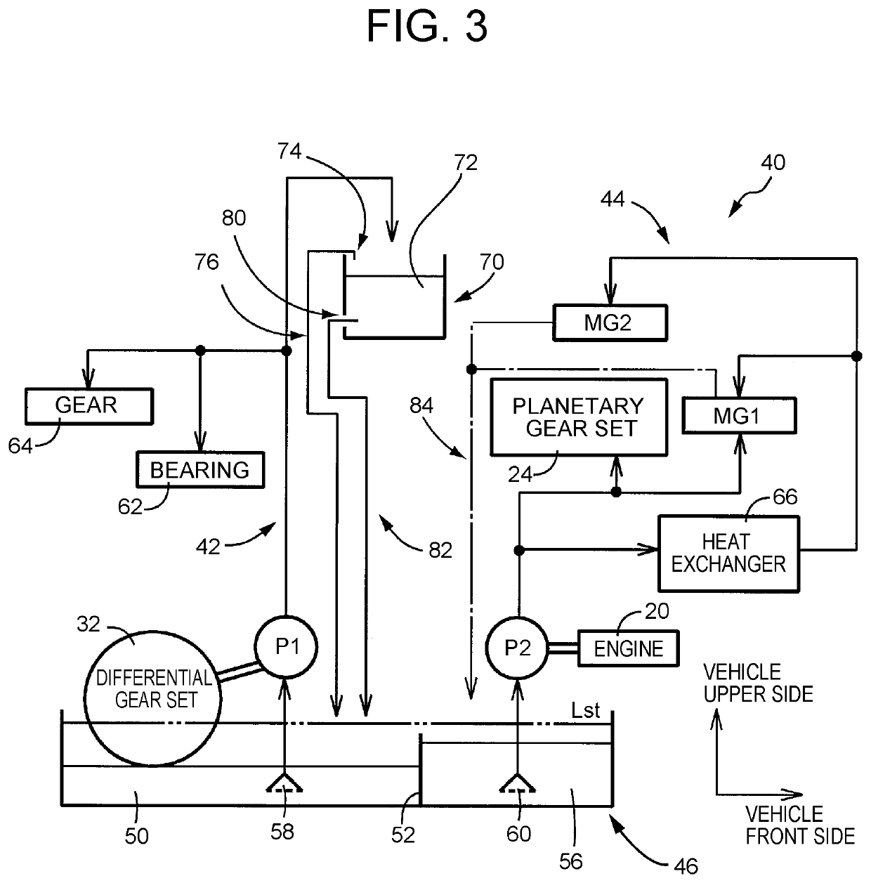
[0052]When the vehicle is moving and the first oil pump P1 and the second oil pump P2 are operating, the oil level decreases to below the position of the upper end of the partition wall 52 as the lubricating oil is scraped up by the differential ring gear Gd etc. that rotate according to the vehicle speed V and as the lubricating oil is suctioned by the first oil pump P1 and the second oil pump P2. The oil level in the first oil storage part 50 is determined by the balance between the amount of lubricating oil scraped up by the differential ring gear Gd etc. plus the amount of lubricating oil suctioned by the first oil pump P1 and the amount of lubricating oil returning to the first oil storage part 50. The oil level in the second oil storage part 56 is determined by the balance between the amount of lubricating oil suctioned by the second oil pump P2 and the amount of lubricating oil returning to the second oil storage part 56. In the first embodiment, the amount of lubricating oil...

second embodiment

[0068]Thus, the lubricating oil is returned from the second outlet 202 to the second oil storage part 56 even when the amount of lubricating oil stored in the third oil storage part 72 is small. Since the lubricating oil is returned from the second outlet 202 to the second oil storage part 56 even when the oil level in the first oil storage part 50 is not significantly low, a significant decrease in the oil level in the first oil storage part 50 can be avoided as well as the oil level in the second oil storage part 56 can be stably maintained.

[0069]FIG. 6 is a hydraulic circuit diagram illustrating a lubricating system 300 of the vehicle transmission device 12 in a third embodiment of the present disclosure. As shown in FIG. 6, the lubricating system 300 of the third embodiment includes a third oil storage part 302. The third oil storage part 302 is divided by a partition wall 304 in the vehicle length direction, into a vehicle front-side storage part 302a and a vehicle rear-side s...

third embodiment

[0071]Thus, the third oil storage part 302 is divided by the partition wall 304 into the vehicle front-side storage part 302a and the vehicle rear-side storage part 302b, and the lubricating oil is supplied to the vehicle front-side storage part 302a by the first oil pump P1. Moreover, the partition wall 304 restricts an equilibrium between the oil levels in the vehicle front-side storage part 302a and the vehicle rear-side storage part 302b while allowing a flow of lubricating oil therebetween. Thus, when the lubricating oil is controlled so as to flow out of one or both of the first outlet 306 and the second outlet 308 based on the amount of lubricating oil stored in the third oil storage part 302, i.e., the level of the lubricating oil therein, there are fewer design restrictions in that it is not necessary to provide the first outlet 306 above the second outlet 308 in the vehicle height direction, so that, for example, the first outlet 306 and the second outlet 308 can be provi...


PUM


Abstract

A lubricating system of a vehicle transmission device includes a third oil storage part that is provided above a first oil storage part and a second oil storage part in a vehicle height direction. The third oil storage part stores lubricating oil, and includes a first outlet that allows the lubricating oil to flow out by gravity toward the first oil storage part without passing through the second oil storage part. As the lubricating oil is thus returned from the first outlet to the first oil storage part without passing through the second oil storage part, the oil level in the first oil storage part can be stably maintained with the lubricating oil supplied thereto regardless of the oil level in the second oil storage part.

Description

CROSS-REFERENCE TO RELATED APPLICATIONS[0001]The disclosure of Japanese Patent Application No. 2017-120905 filed on Jun. 20, 2017 including the specification, drawings and abstract is incorporated herein by reference in its entirety.BACKGROUND1. Technical Field[0002]The present disclosure relates to a lubricating system of a vehicle transmission device, and more particularly to a lubricating system of a vehicle transmission device that can stably maintain the level of lubricating oil stored in an oil storage part provided at a bottom of a case.2. Description of Related Art[0003]A lubricating system of a vehicle transmission device that includes a case, a first oil storage part, a second oil storage part, a first oil pump, and a second oil pump as described below is known. The case is a case in which a gear mechanism of the vehicle transmission device that transmits drive power from a drive power source to drive wheels is contained and at a bottom of which lubricating oil is stored. ...

Claims


Application Information

Patent Timeline
Patent Type & Authority Patents(United States)
IPC IPC(8): F16H57/04
CPCF16H57/045F16H57/0441F16H57/0482F16H57/0447F16H57/04F16H57/0421F16H57/0434
Inventor KIYOKAMI, HIROAKIIWAKURA, KAZUKI
Owner TOYOTA JIDOSHA KK
Why Eureka
Try Eureka