Dynamic interrupt rate control in computing system

a technology of interrupt rate and computing system, applied in the direction of program control, multi-programming arrangement, instruments, etc., can solve the problems of user frustration and dissatisfaction with the device, the operating time is reduced, and the device performance is typically reduced as well

Active Publication Date: 2020-08-18
ADVANCED MICRO DEVICES INC
View PDF53 Cites 2 Cited by
  • Summary
  • Abstract
  • Description
  • Claims
  • Application Information

AI Technical Summary

Benefits of technology

[0005]While the immediate handling of interrupts as described above provides for improved performance, it increases power consumption. While this may be the most straightforward way of ensuring the performance of a device remains high, in some cases the immediate handling of interrupts may not be necessary for maintaining a satisfying user experience. In view of the above, system and methods are desired for enabling more efficient power management are desired.

Problems solved by technology

In the case of battery operated computing devices, reducing power consumption can mean longer operating times before the battery must be recharged.
Whatever the reason, one of the drawbacks of reducing power consumption is that the performance of the device is typically reduced as well.
If the performance of a device (e.g., a laptop, mobile phone, gaming console, etc.) is noticeably degraded due to mechanisms within the device to reduce power consumption, users become frustrated and dissatisfied with the device.
As a consequence, users may not purchase the device.
One activity that interferes with the idle state of a CPU is the handling of interrupts.
When interrupts are handled as they come in, the CPU may be caused to enter and exit an idle state repeatedly which in turn reduces the effectiveness of the idle state on reducing power consumption.
While the immediate handling of interrupts as described above provides for improved performance, it increases power consumption.

Method used


Image

  • Dynamic interrupt rate control in computing system
  • Dynamic interrupt rate control in computing system
  • Dynamic interrupt rate control in computing system

Examples


Embodiment Construction

[0012]In the following description, numerous specific details are set forth to provide a thorough understanding of the methods and mechanisms presented herein. However, one having ordinary skill in the art should recognize that the various embodiments may be practiced without these specific details. In some instances, well-known structures, components, signals, computer program instructions, and techniques have not been shown in detail to avoid obscuring the approaches described herein. It will be appreciated that for simplicity and clarity of illustration, elements shown in the figures have not necessarily been drawn to scale. For example, the dimensions of some of the elements may be exaggerated relative to other elements.

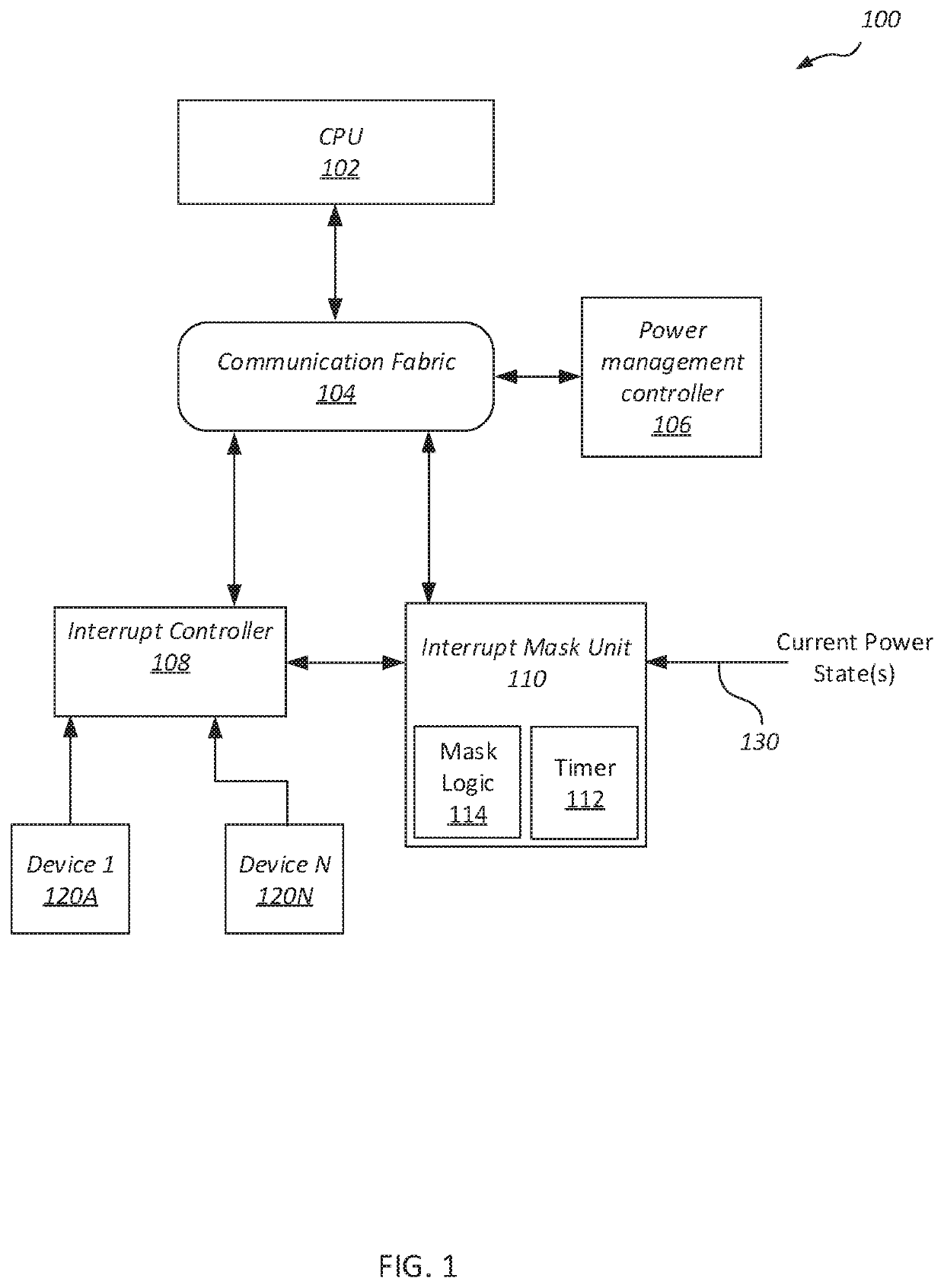
[0013]Various systems, apparatuses, and methods for masking and unmasking interrupts in a computing system are disclosed herein. Interrupts that are masked have their servicing intentionally delayed and are coalesced for a period of time during which they are not...


PUM


Abstract

Systems, apparatuses, and methods for intentionally delaying servicing of interrupts in a computing system are disclosed. A computing system includes a processor that services interrupts generated by components of the computing system. An interrupt controller detects a received interrupt and intentionally delays servicing of the interrupt depending on various conditions. If the interrupt is a first type of interrupt and the processor is in a first power state, servicing of the interrupt is delayed by a first period of time. If the interrupt corresponds to the first type of interrupt and the processor is in a second power state, servicing of the interrupt is delayed for a period of time that is longer than the first period of time. If a non-maskable interrupt is received before expiration of either the first or second period of time, then servicing of any previously delayed interrupts is allowed to proceed.

Description

PRIORITY INFORMATION[0001]This application claims benefit of priority to Indian Application No. 201711042849, entitled “Dynamic Interrupt Rate Control In Computing Systems”, filed, Nov. 29, 2017, the entirety of which is incorporated herein by reference.BACKGROUNDDescription of the Relevant Art[0002]Modern processors include a variety of circuits and components to facilitate fast and efficient computation. In addition, circuits and components are included to manage communications between devices, including devices external to the processor. For example, input / output (I / O) controllers are generally included to manage communications with external devices such as display devices, external storage devices, network communications, as well as various other peripheral devices. In order to communicate with these devices, transactions are conveyed from, and received by, processing elements of the processor (e.g., central processing units, graphics processing units, etc.).[0003]In recent year...

Claims


Application Information

Patent Timeline
Patent Type & Authority Patents(United States)
IPC IPC(8): G06F1/329G06F9/50G06F9/48
CPCG06F9/4812G06F1/329G06F9/5027G06F9/5094Y02D10/00
Inventor GADA, SRIDHAR V.BRANOVER, ALEXANDER J.
Owner ADVANCED MICRO DEVICES INC
Why Eureka
Try Eureka