

Method for identifying a correct operation of an electrical switching unit, computer program product for executing such a method, and full bridge circuit with a control device for executing such a method
a technology of correct operation and electrical switching unit, which is applied in the direction of pulse generator, pulse technique, instruments, etc., can solve the problems of failure to detect fault or short circuit occurring in electrical switching unit, failure to carry out and not always with the required reliability, so as to achieve the effect of more reliable identification of correct operation of electrical switching uni
- Summary
- Abstract
- Description
- Claims
- Application Information
AI Technical Summary
Benefits of technology
Problems solved by technology
Method used
Image


Examples
Embodiment Construction
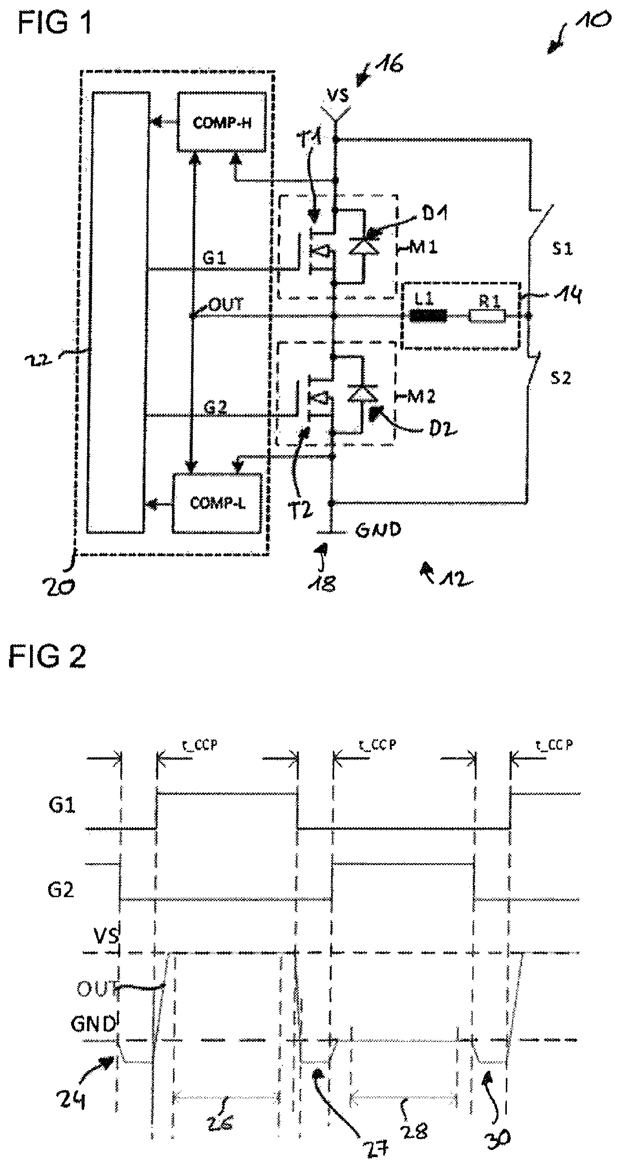
[0032]Reference is made first to FIG. 1, which shows an electrical switching unit 10 with a full bridge circuit 12 and an inductive load 14. The full bridge circuit 12 has a first semiconductor switching element M1 and a second semiconductor switching element M2. The full bridge circuit 12 also has a first switch S1 and a second switch S2, and an inductive load (represented by a coil L1 and a resistor R1) arranged between the bridge branches. The inductive load 14 can be a motor and, in particular a motor for driving an opening element such as a door or tailgate of a vehicle, or can be a different inductive load such as a solenoid valve, for example.
[0033]The first semiconductor switching element M1 is used to supply the inductive load 14 with a first supply voltage potential 16 and the second semiconductor switching element M2 is used to supply the inductive load 14 with a second supply voltage potential 18, the second supply voltage potential 18 having a lower value compared to th...
PUM
 Abstract
Description
Claims
Application Information