Electrochemical reaction unit cell, and electrochemical reaction cell stack

a technology of electrochemical reaction and unit cell, which is applied in the manufacture of cell components, electrochemical generators, and final product manufacturing, etc., can solve the problems of poor electricity generation performance of unit cell, and achieve the effects of preventing the diffusion of sr, high resistance, and preventing the performan

Active Publication Date: 2020-08-25
MORIMURA SOFC TECH CO LTD
View PDF7 Cites 0 Cited by
  • Summary
  • Abstract
  • Description
  • Claims
  • Application Information

AI Technical Summary

Benefits of technology

[0010]The above object has been achieved by providing an electrochemical reaction unit cell (1) comprising an electrolyte layer containing Zr, an anode disposed on one side of the electrolyte layer in a first direction, a cathode containing Sr and disposed on another side of the electrolyte layer in the first direction, and a reaction preventing layer disposed between the electrolyte layer and the cathode, wherein the reaction preventing layer contains Zr in an amount of 0.015 (wt %) to 1 (wt %). According to the electrochemical reaction unit cell (1), since the reaction preventing layer contains Zr in an amount of 0.015 (wt %) or more. Sr diffused from the cathode toward the electrolyte layer can be trapped by Zr distributed in the reaction preventing layer. This can prevent diffusion of Sr into a region in the vicinity of the boundary between the reaction preventing layer and the electrolyte layer, and can prevent the performance of the electrochemical reaction unit cell from becoming impaired, which would otherwise occur due to generation of stratiform SrZrO3 of high resistance in the region. Since the reaction preventing layer contains Zr in an amount of 1 (wt %) or less, excessive diffusion of an element (other than Sr) from the cathode can be prevented, thereby preventing a reduction in reliability, which would otherwise occur due to a variation in the composition of the cathode.
[0011]In a preferred embodiment (2) of the electrochemical reaction unit cell (1), the reaction preventing layer contains Zr in an amount of 0.18 (wt %) or less. According to the electrochemical reaction unit cell (2), since the reaction preventing layer contains Zr in an amount of 0.18 (wt %) or less, excessive diffusion of an element (other than Sr) from the cathode can be prevented even after initiating use of the unit cell. Consequently, a reduction in endurance reliability is prevented, which would otherwise occur due to a variation in the composition of the cathode after initiating use of the unit cell.
[0012]In another preferred embodiment (3) of the electrochemical reaction unit cell (1) or (2) above, the reaction preventing layer contains Zr in an amount of 0.05 (wt %) or more. According to the electrochemical reaction unit cell (3), since the reaction preventing layer contains Zr in an amount of 0.05 (wt %) or more, Sr diffused from the cathode toward the electrolyte layer can be effectively trapped by Zr distributed in the reaction preventing layer, thereby effectively preventing the performance of the electrochemical reaction unit cell from becoming impaired.
[0013]In yet another preferred embodiment (4) of the electrochemical reaction unit cell of any of (1) to (3) above, the reaction preventing layer contains Gd. According to the present electrochemical reaction unit cell, Gd contained in the reaction preventing layer can prevent diffusion of Sr toward the electrolyte layer, thereby effectively preventing the performance of the electrochemical reaction unit cell from becoming impaired.
[0014]In yet another preferred embodiment (5) of the electrochemical reaction unit cell of any of (1) to (4) above, the electrolyte layer contains a solid oxide. According to the electrochemical reaction unit cell (5), impairment of the performance of the unit cell, which would otherwise occur due to generation of SrZrO3, can be prevented while preventing a reduction in the reliability of the cathode.
[0015]In yet another preferred embodiment (6), the electrochemical reaction unit cell of any of (1) to (5) above is a fuel cell unit cell. According to the electrochemical reaction unit cell (6), impairment of electricity generation performance can be prevented while preventing a reduction in the reliability of the cathode.

Problems solved by technology

The generation of stratiform SZO in a region between the cathode and the electrolyte layer (i.e., continuous generation of SZO in a direction approximately perpendicular to the first direction) increases the electric resistance in the first direction, resulting in poor electricity generation performance of the unit cell.

Method used


Image

  • Electrochemical reaction unit cell, and electrochemical reaction cell stack
  • Electrochemical reaction unit cell, and electrochemical reaction cell stack
  • Electrochemical reaction unit cell, and electrochemical reaction cell stack

Examples


embodiment

A. Embodiment

A-1. Structure:

(Structure of Fuel Cell Stack 100)

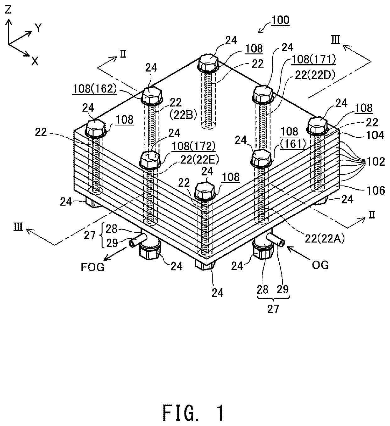
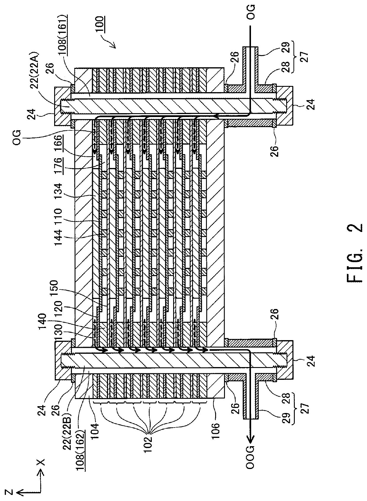
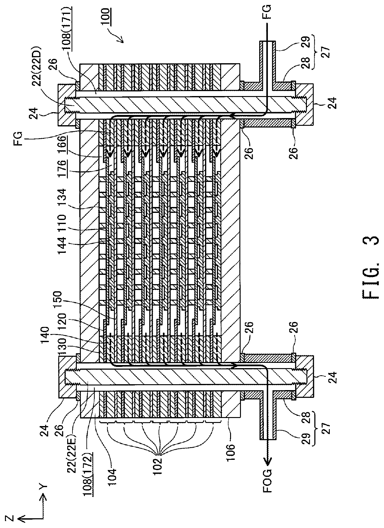
[0030]FIG. 1 is a perspective view showing the external appearance of a fuel cell stack 100 according to an embodiment of the present invention; FIG. 2 is an explanatory view showing an XZ section of the fuel cell stack 100 taken along line II-II of FIG. 1; and FIG. 3 is an explanatory view showing a YZ section of the fuel cell stack 100 taken along line III-III of FIG. 1. FIGS. 1 to 3 show mutually orthogonal X-axis. Y-axis, and Z-axis for specifying orientation. In the present specification, the positive Z-axis direction is called the “upward direction” and the negative Z-axis direction is called the “downward direction”; however, in actuality, the fuel cell stack 100 may be disposed in a different orientation. The same also applies to FIG. 4 and subsequent drawings.

[0031]The fuel cell stack 100 includes a plurality of (seven in the present embodiment) of electricity generation units 102 and a pair of end plates 104 and...


PUM

PropertyMeasurementUnit
temperatureaaaaaaaaaa
BET specific surface areaaaaaaaaaaa
thicknessaaaaaaaaaa

Abstract

An electrochemical reaction unit cell including an electrolyte layer containing Zr, an anode disposed on one side of the electrolyte layer in a first direction, a cathode containing Sr and disposed on another side of the electrolyte layer in the first direction, and a reaction preventing layer disposed between the electrolyte layer and the cathode. The reaction preventing layer contains Zr in an amount of 0.015 wt % to 1 wt %.

Description

CROSS-REFERENCE TO RELATED APPLICATIONS[0001]This application is a 371 of International Application No. PCT / JP2017 / 018758 filed May 19, 2017, which claims priority from Japanese Patent Application No. 2016-156051 filed Aug. 9, 2016.BACKGROUND OF THE INVENTION1. Field of the Invention[0002]The present disclosure relates to an electrochemical reaction unit cell.2. Description of the Related Art[0003]A known type of a fuel cell for generating electricity by utilizing an electrochemical reaction between hydrogen and oxygen is a solid oxide fuel cell (hereinafter also referred to as a “SOFC”). A unit cell of a fuel cell (hereinafter also referred to as a “unit cell”), which is a constitutive unit of a SOFC, and includes an electrolyte layer containing a solid oxide, a cathode, and an anode such that the cathode and the anode face each other in a predetermined direction (hereinafter referred to as a “first direction”) and the electrolyte layer is arranged between these electrodes. The ele...

Claims


Application Information

Patent Timeline
Patent Type & Authority Patents(United States)
IPC IPC(8): H01M8/1246H01M4/86H01M4/90H01M8/1213H01M8/1253H01M4/88H01M8/2425H01M8/124H01M8/02
CPCH01M4/9033H01M8/1213H01M4/8657H01M4/8621H01M8/02H01M4/9025H01M8/1246H01M2300/0071Y02E60/50H01M4/8882H01M8/1253H01M4/881H01M2008/1293H01M4/8828H01M2300/0094H01M8/2425Y02P70/50
Inventor INOUE, SHIROONO, TATSUYA
Owner MORIMURA SOFC TECH CO LTD
Why Eureka
Try Eureka