Switching frequency methods and apparatus for ambient backscatter networking and jamming

a technology of switching frequency and ambient backscatter, applied in the direction of transmission, duplex signal operation, electric apparatus, etc., can solve the problems of increasing complexity and cost of the overall system, and achieve the effect of increasing the reliability of backscatter communication and reliable backscatter communication

Active Publication Date: 2020-09-01
VOUGIOUKAS GEORGIOS +1
View PDF2 Cites 5 Cited by
  • Summary
  • Abstract
  • Description
  • Claims
  • Application Information

AI Technical Summary

Benefits of technology

[0007]A short training sequence backscattered from the tag is utilized for acquiring a tag and wireless channel related phase. The methods and apparatus of embodiments of this invention allows for reliable backscatter communication; the existence of modulation at the ambient illuminator is turned to an advantage by this i...

Problems solved by technology

Moreover, current methods require multiple access from multiple tags utilizing time division multiple ac...

Method used


Image

  • Switching frequency methods and apparatus for ambient backscatter networking and jamming
  • Switching frequency methods and apparatus for ambient backscatter networking and jamming
  • Switching frequency methods and apparatus for ambient backscatter networking and jamming

Examples


Embodiment Construction

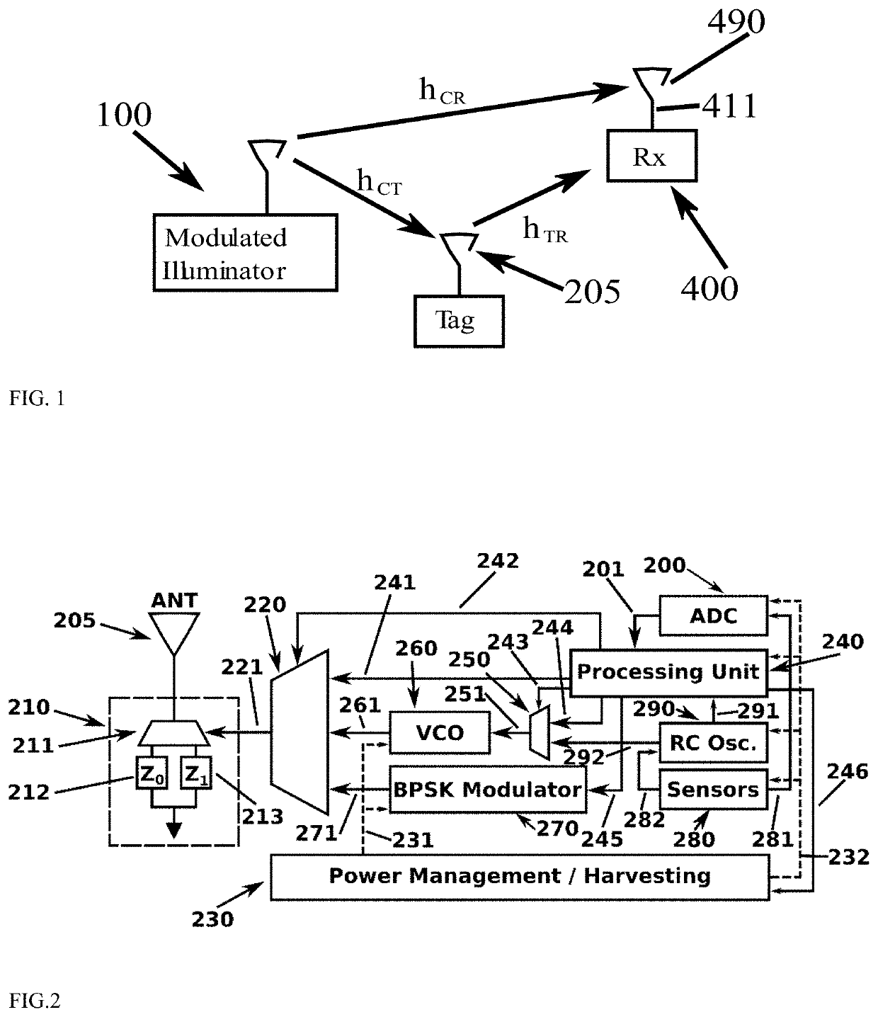
[0020]An illuminator 100 transmits a modulated signal, destined to its own, legacy receiver (FIG. 1). The same signal illuminates the tag antenna 205 in FIG. 1; the tag modulates its own information on the already modulated illuminating signal, by careful reflection. The tag antenna-reflected signal is received by the receiver (Rx) 400, through the receiver antenna 490 (FIG. 1).

[0021]One embodiment of part of the invention, the backscatter tag, is shown in FIG. 2. Backscatter tag consists of an antenna 205 connected to a radio frequency (RF) termination switching module 210. The RF switching module consists of a RF switch 211 and two complex impedances 212 and 213. Antenna 205 is connected to either complex impedance (load) Z0 212 or complex impedance (load) Z1 213 by RF switch 211.

[0022]Load connected to the tag antenna, at any given time instant, is selected based on the value of a binary signal 221, driving the RF switch. Binary signal 221 is the output of a multiplexer 220. Base...


PUM


Abstract

Two ambient backscatter modulation methods and embodiments are disclosed, pseudo FSK and shifted BPSK. Embodiments of a receiver of signals for those modulations are also disclosed. Both methods disclosed allow for frequency-based networking of multiple backscatter devices when signals from an ambient, modulated radio frequency (RF) source are used for illumination. Disclosed method and apparatus exploit the inherent variation of the ambient modulated illuminating signal and offers performance improvement. Aspects of the disclosed invention also provide methods for passive jamming of full duplex transceivers and methods for assisting RF source localization.

Description

BACKGROUND OF THE INVENTION[0001]The present invention is in the technical field of wireless transmission and reception of information. More particularly, the present invention is in the technical field of ultra-low power backscatter radio communication. Embodiments and aspects of part of the invention described herein, focus on digital bistatic backscatter radio; the illuminator of a tag and the receiver of the backscattered information (from the tag) are distinct units, located at different points in space.[0002]The illuminating signal may be modulated and / or emitted from legacy wireless systems or infrastructure (ambient case).[0003]Embodiments and aspects of part of the invention described herein, are inspired by recent findings in digital bistatic backscatter radio [Bletsas et al 12a], [Bletsas et al 12b], [Bletsas et al 13] (where the illuminating signal is unmodulated) and ambient backscatter radio (where the illuminating signal is modulated and carries its own information). ...

Claims


Application Information

Patent Timeline
IPC IPC(8): H04B1/40H04L5/14H04K3/00H04B1/30
CPCH04B1/40H04B1/30H04K3/60H04L5/14
Inventor VOUGIOUKAS, GEORGIOSBLETSAS, AGGELOS
Owner VOUGIOUKAS GEORGIOS
Why Eureka
Try Eureka