Method of handling a wind turbine rotor blade pitch bearing unit

a technology of rotor blade and rotor blade, which is applied in the direction of machines/engines, mechanical equipment, and final product manufacturing, etc., can solve the problems of not being able to access the pitch bearing easily, requiring maintenance or replacement, and the type of pitch bearing is subject to wear and tear

Active Publication Date: 2020-09-29
SIEMENS GAMESA RENEWABLE ENERGY AS
View PDF16 Cites 0 Cited by
  • Summary
  • Abstract
  • Description
  • Claims
  • Application Information

AI Technical Summary

Benefits of technology

[0007]An aspect relates to providing a more economical way of removing the pitch bearing unit of a wind turbine rotor blade in a maintenance procedure.
[0009]An advantage of the bearing unit handling method according to embodiments of the invention is that there is no need to use a large crane of the type described above. A defective bearing unit can therefore be removed and replaced by a replacement bearing unit in a cost-effective manner. In the case of an offshore wind turbine, a significant reduction in costs can be achieved by not having to pay for an installation vessel or a vessel big enough to support a large crane.
[0011]An advantage of the bearing unit handling arrangement is that it can be realized with relatively low cost effort. The bearing unit handling arrangement allows replacement of a defective bearing unit without actually having to completely detach the rotor blade from the hub. During the entire handling manoeuvre, the blade remains connected to the hub, and a bearing unit is removed or inserted through the gap.
[0013]The wind turbine according to embodiments of the invention is equipped with a means to facilitate the performance of maintenance procedures on the bearing unit(s), avoiding the need for an installation crane or other large crane, so that the costs of such manoeuvres can be kept to a favourably low level.
[0021]In a further preferred embodiment of the invention, the pitch bearing unit displacement assembly comprises a pivot arranged between the pitch bearing unit and the hub. Such a pivot is preferably arranged close to the outer edge of the bearing unit, so that a rotation of the bearing unit about its pivot has the effect of moving the bearing unit almost completely outside the space between hub and blade. Similarly to the approach described above, a hoist unit mounted to the nacelle or hub can then be used to lower the bearing unit to ground level.

Problems solved by technology

Any kind of pitch bearing is subject to wear and tear, and may eventually require maintenance or replacement.
However, it is not easy to access a pitch bearing when installed in a large wind turbine, especially in the case of an offshore wind turbine.
Crane time is expensive for this type of crane, so that repair and maintenance procedures that require their use are generally very costly.

Method used


Image

  • Method of handling a wind turbine rotor blade pitch bearing unit
  • Method of handling a wind turbine rotor blade pitch bearing unit
  • Method of handling a wind turbine rotor blade pitch bearing unit

Examples


first embodiment

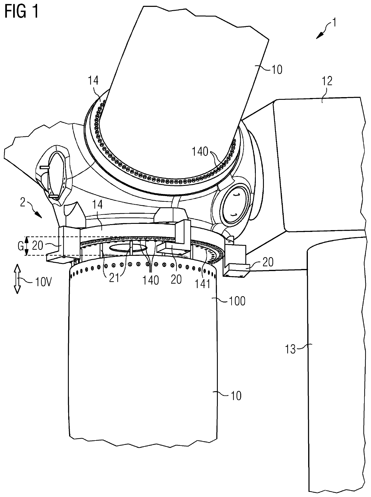
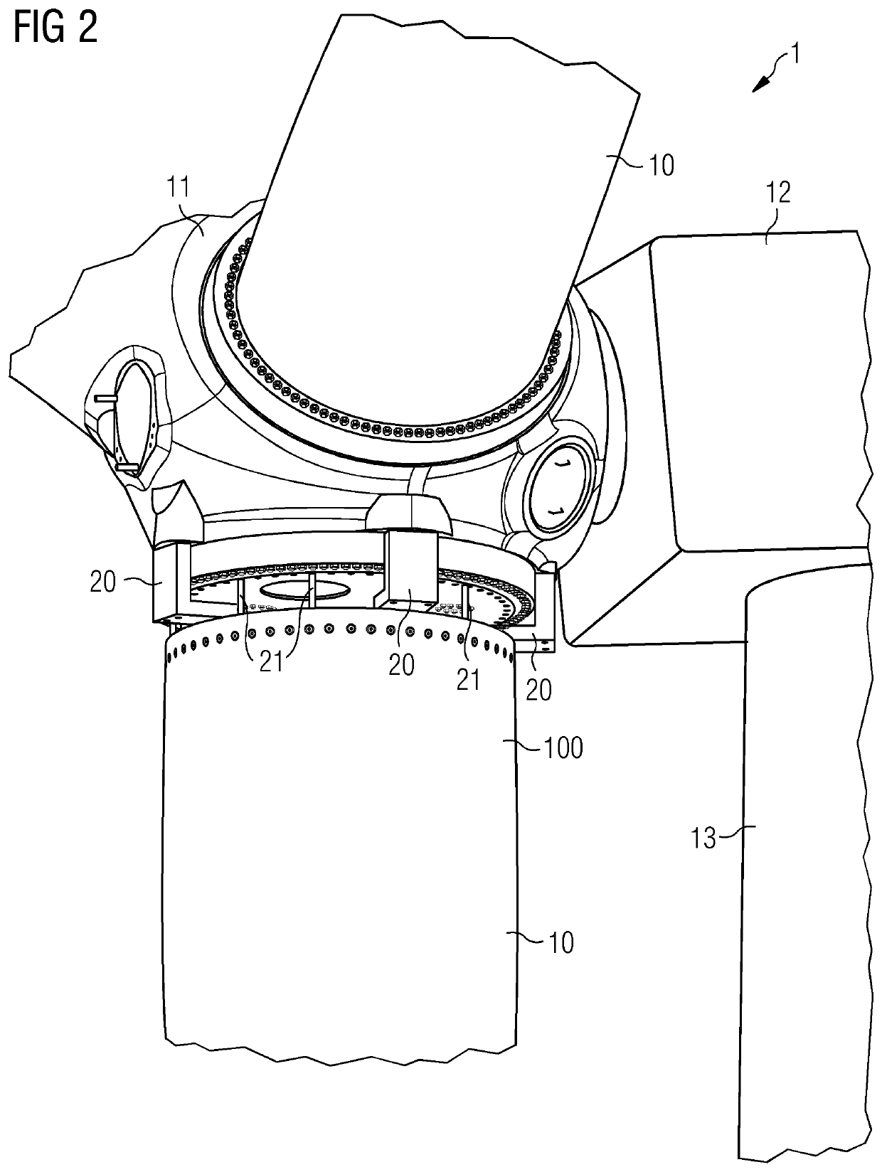
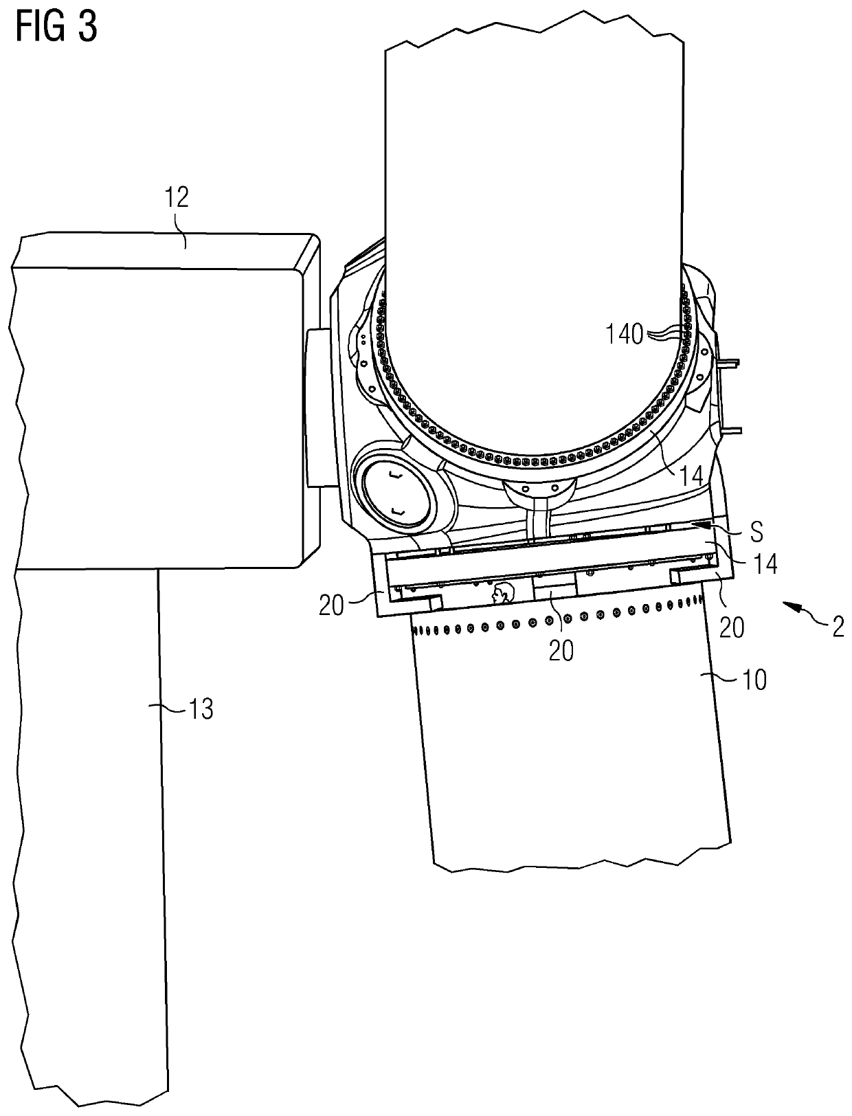
[0039]FIGS. 4-5 show further stages during the pitch bearing exchange procedure of FIGS. 1-3, using a bearing unit displacement assembly 22, 220. Here, a pivot 22 is permanently installed in the nacelle 12. For a bearing exchange procedure, a pivot arm 220 is mounted to the nacelle pivot 22. The pivot arm 220 can rotate about the nacelle pivot 22 in the direction 22R shown, and can enter the space S between bearing unit 14 and hub 11, so that a worker (inside the hub) can secure the bearing unit 14 to the pivot arm 22. Alternatively, the pivot arm 220 can enter the gap G between blade root end 100 and bearing unit 14, so that a worker inside the blade root end can secure the bearing unit 14 to the pivot arm 22.

second embodiment

[0040]In FIG. 5, a hoist unit 25, for example a small crane 25, is shown in place on top of the nacelle 12. This hoist unit 25 can be stowed in the nacelle 12 when not in use. A cable or chain can be secured to the bearing unit 14, for example by a maintenance worker inside the hub or blade root end. The hoist unit 25 can then lower the defective bearing unit 14 to ground level, where it is detached. If the pivot arm 220 was mounted to the bearing unit 14 from below, the entire pivot arm 220 may be detached from the nacelle pivot 22 and lowered to ground level along with the bearing unit 14. A replacement bearing unit 14′ can then be attached to the hoist unit 25 (and pivot arm 220, as the case my be) and raised to hub height, where the steps described above are performed in the reverse order to install the replacement bearing unit 14′ between hub 11 and rotor blade 10. After completion of the exchange manoeuvre, any temporary apparatus such as the extension rods, fixation brackets,...

third embodiment

[0041]FIG. 8 shows a further stage during the pitch bearing exchange procedure of FIGS. 1-3, using a bearing unit displacement assembly. Here, rail assemblies 24 are mounted between the bearing unit 14 and the hub 11, so that the bearing unit 14 can slide outwards, essentially horizontally in the direction 24H shown (a slight upwards tilt of the generator rotational axis may be assumed to exist to avoid tower / blade collisions). In this embodiment, a hoist unit 25 is temporarily mounted on top of the hub 11, so that it can be connected by cable or wire to the bearing unit 14 in order to lower the bearing unit 14 to ground level.

[0042]FIG. 9 shows the lowering of a bearing unit 14 to “ground level” during a pitch bearing exchange procedure, in this case to a marine vessel 90 near the tower of an offshore wind turbine. A defective bearing 14 at the interface 101 between blade 10 and hub 11 can be replaced with a minimum of cost and effort since a crane, large enough to reach to hub hei...


PUM


Abstract

A method of handling the pitch bearing unit of a rotor blade mounted to the hub of a wind turbine, the method including the steps of providing an extension assembly at the interface between the rotor blade and the hub, moving the rotor blade outward from the hub by means of the extension assembly to open a gap large enough to accommodate the pitch bearing unit while maintaining a connection between the rotor blade and the hub, and removing the pitch bearing unit through the gap.

Description

CROSS-REFERENCE TO RELATED APPLICATIONS[0001]This application claims priority to European application No. EP16177271.0 having a filing date of Jun. 30, 2016, the entire contents of which are hereby incorporated by reference.FIELD OF TECHNOLOGY[0002]The following describes a method of handling a pitch bearing unit of a wind turbine rotor blade, a pitch bearing unit handling arrangement; and a wind turbine.BACKGROUND[0003]Wind turbines with several megawatts power output are generally very tall structures, since long rotor blades are required in order to achieve such power output levels. In order to extract the maximum amount of energy from the wind, the rotor blades of a wind turbine can be controlled by a pitch system so that each blade can be optimally pitched into the wind. To this end, the root end of a rotor blade is usually circular, so that it can be mounted to a circular pitch bearing. There are various ways of realizing a pitch bearing for a rotor blade. For example, a tooth...

Claims


Application Information

Patent Timeline
Patent Type & Authority Patents(United States)
IPC IPC(8): F03D13/10F03D80/50F03D80/70F03D7/02F03D1/06
CPCF03D80/70F03D1/0658F03D80/50F03D7/0224F03D13/10F03D1/065Y02E10/72Y02P70/50F05B2230/80F05B2230/70F05B2230/61F05B2230/60
Inventor EBBESEN, HENNINGLAURSEN, CHRISTIAN
Owner SIEMENS GAMESA RENEWABLE ENERGY AS
Why Eureka
Try Eureka