Eureka AIR delivers breakthrough ideas for toughest innovation challenges, trusted by R&D personnel around the world.

Device and method for decontaminating soil

a technology of decontamination device and soil, which is applied in the direction of lighting and heating apparatus, transportation and packaging, combustion types, etc., can solve the problems of contaminated materials posing environmental risks, and the remediation system to clean contaminated materials rely on inefficient processes. , to achieve the effect of avoiding secondary use of gas, dissipating heat, and avoiding contaminated materials

Active Publication Date: 2020-10-13
IRON CREEK GRP HLDG INC
View PDF30 Cites 0 Cited by
  • Summary
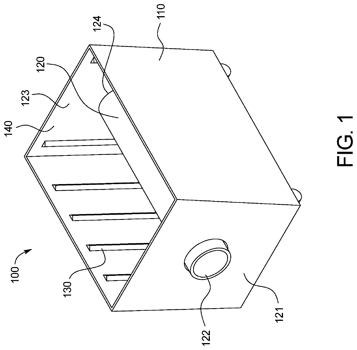
  • Abstract
  • Description
  • Claims
  • Application Information

AI Technical Summary

Benefits of technology

[0003]Current remediation systems expend large amounts of energy to achieve and sustain desorption temperatures and durations due to inefficient processes; current systems typically operate at roughly 30% efficiency. Current systems force heated air into a contaminated material directly to induce desorption, resulting in a large loss of heated air exhausted to the atmosphere and increasing the volatility of contaminated vapors released by desorption. This volatility is a function of the interaction of the oxygen in the injected heated air chemically reacting with the contaminated vapor.
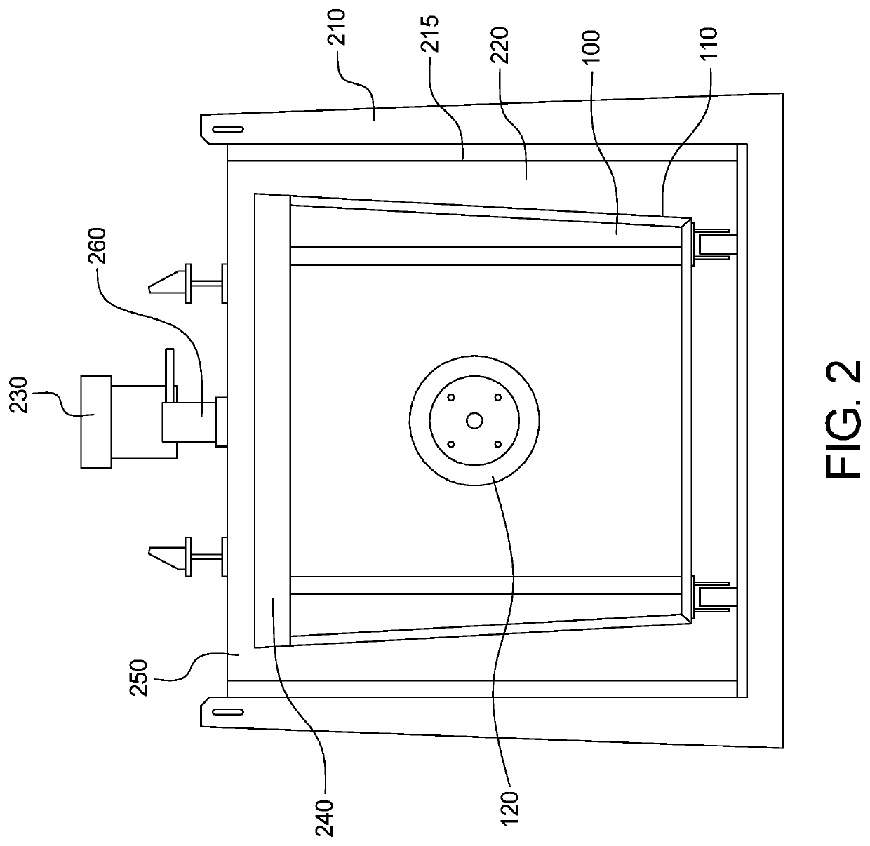
[0004]Some embodiments of the present disclosure indirectly heat contaminated materials that are stored in a reduced-oxygen or oxygen-free environment to reduce volatilization of the contaminated vapor. Additionally, by indirectly heating the contaminated material, the control of the flow of heat applied to the contaminated material is improved and loss of heating air or other heating gas is reduced. These embodiments can operate at lower temperatures than conventional remediation or desorption systems as the efficiency savings and control of the flow of the heating agent enables longer durations of remediation without increasing the energy expended. A benefit of lower operating temperatures is easier permit or license acquisition to establish a remediation site, thereby greatly increasing the available locations for conducting remediation of contaminated material.
[0006]This dual heating system indirectly heats the contaminated material by providing inside-out heating from the core heating conduit and outside-in heating from the space within the bin housing insulator. Energy efficiency by preserving heat from the heated gas rather than directly injecting into the contaminated material and releasing into the atmosphere, as currently available systems typically do, results in thermal efficiency in embodiments of the present disclosure to ranges between 70% and 90%, as compared to 30% of currently available systems as described above. Additionally, injecting heated gas directly into contaminated material quickly dissipates the heat of the gas and precludes secondary use of the gas as a heating agent, requiring a constant stream of heated gas through a contaminated material to maintain appropriate temperatures. Some embodiments avoid this dissipation of heat and correspondingly improve the efficiency of the system.
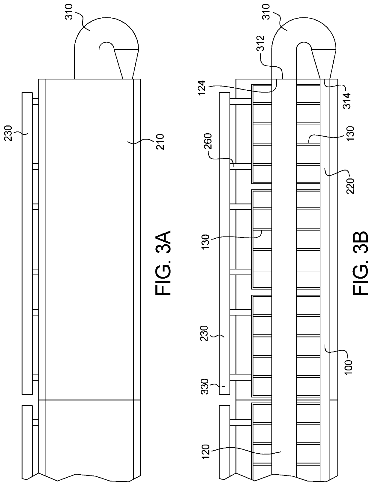
[0007]In some embodiments, offgas, such as contaminated vapors, released by desorption from the heated contaminated material can exit the bin through vapor outlets within the bin coupled to extensions for transporting the offgas from the interior of the bin to an exterior collection point. In some embodiments, the vapor outlets include perforations to enable migration of the offgas into the vapor outlets without physically disturbing the contaminated material to expose and release the offgas. By removing a need to physically manipulate the contaminated material, such as by an auger or rotation of the bin as performed in current systems, additional energy savings are achieved. Further, with fewer mechanical parts, embodiments of the present disclosure require less maintenance and are safer to operate by technicians. An additional benefit of fewer mechanical parts is the lack of prescreening materials for remediation. Current systems require rocks or other debris to be removed from the contaminated material prior to remediation to reduce interference with the mechanical operations within the desorption system. The desorption by dual indirect heating of a bin with vapor outlets rather than mechanical manipulation tools precludes the need for prescreening contaminated material, enabling faster deployment and reduced preparation time to being decontaminating a material.
[0008]In some embodiments, offgas from the vapor outlets through extensions are collected in an exhaust header. In some embodiments, the exhaust header is external to the desorption system and is separated from the heating process, such that when offgas is collected in the exhaust header it may condense for recovery. As the desorption occurs in a low oxygen or oxygen free environment, the offgas is not oxidized and any condensed contaminant making up the offgas is more easily recovered.
[0009]Some embodiments may be modular, to permit remediation in batches scaled to be project-specific size. For example, the size of a bin, core heating conduit, and bin housing insulator may be adjusted larger or smaller to fit the project need; similarly, instead of increasing the size of a single component, some embodiments couple a plurality of components together such as by serially or linearly linking several bins, bin housing insulators, and core heating conduits together. Modular design and deployment allows for “portable” remediation devices relative to currently available systems, and increases the number of sites that may be established as a remediation site. Modular / portable remediation systems further reduce logistical costs of remediation otherwise incurred by moving large volumes of contaminated material to a remediation site, as compared to moving a modular / portable remediation system to a contaminated site.

Problems solved by technology

Industrial processes commonly contaminate material, such as soil, proximate to the location of the process or produce contaminated material as a function of the process itself, such as drilling mud.
These contaminated materials pose environmental risks.
Remediation systems to clean contaminated material rely on inefficient processes.
The size of remediation systems involved limit deployment options and can require transporting the material to another location, adding further costs and limiting recapture options of the contaminated material.
Licenses and permits to operate current remediation systems, especially those that operate at high temperatures, may further preclude decontamination options at given locations.
Current remediation systems expend large amounts of energy to achieve and sustain desorption temperatures and durations due to inefficient processes; current systems typically operate at roughly 30% efficiency.
Current systems force heated air into a contaminated material directly to induce desorption, resulting in a large loss of heated air exhausted to the atmosphere and increasing the volatility of contaminated vapors released by desorption.
First, a contaminated material is indirectly heated by conduction from a core heating conduit traversing the interior of a bin filled with contaminated material.
Additionally, injecting heated gas directly into contaminated material quickly dissipates the heat of the gas and precludes secondary use of the gas as a heating agent, requiring a constant stream of heated gas through a contaminated material to maintain appropriate temperatures.

Method used


Image

  • Device and method for decontaminating soil
  • Device and method for decontaminating soil
  • Device and method for decontaminating soil

Examples


Embodiment Construction

[0018]This disclosure relates to technologies to indirectly heat a material. In some embodiments, the material comprises at least one contaminant. A non-exhaustive list of contaminants that are commonly found in contaminated materials include hydrocarbons, agricultural waste, fertilizers, pesticides, chlorinated solvents, or other manufactured gas plant waste. Some embodiments are further directed to thermally induce physical separation of a contaminant within a contaminated material through desorption induced by dual indirect heating. In some embodiments, an exhaust header recaptures contaminant released as offgas from the material by condensing the offgas in the exhaust header.

[0019]One embodiment of the present disclosure is a thermal desorption device. In some embodiments, a bin housing insulator encloses or encapsulates bins filled with contaminated material. The bin housing insulator further comprises a gas delivery port to provide a flow of heated gas through the desorption d...


PUM


Abstract

A thermal desorption system for remediating contaminated material in a zero oxygen environment by heating a gas and flowing the heated gas through a core heating conduit traversing the interior of a material compartment of a bin filled with contaminated material, redirecting the flow of heated gas from the core heating conduit to a space between the exterior of the bin and the interior of a bin housing insulator encapsulating the bin to provide dual indirect heating to the contaminated material within the bin, directing off gases of contaminated vapors released by desorption from the material to an exhaust header through a plurality of vapor outlets, and condensing the offgas in the exhaust header.

Description

BACKGROUND OF THE INVENTION[0001]Industrial processes commonly contaminate material, such as soil, proximate to the location of the process or produce contaminated material as a function of the process itself, such as drilling mud. These contaminated materials pose environmental risks. Remediation systems to clean contaminated material rely on inefficient processes. Further, material properties of the underlying material may be altered during a remediation process, precluding restoration applications. The size of remediation systems involved limit deployment options and can require transporting the material to another location, adding further costs and limiting recapture options of the contaminated material. Licenses and permits to operate current remediation systems, especially those that operate at high temperatures, may further preclude decontamination options at given locations.SUMMARY[0002]Devices, systems, and methods to provide remediation of contaminant in a material by deso...

Claims


Application Information

Patent Timeline
Patent Type & Authority Patents(United States)
IPC IPC(8): B09C1/06F23G7/14B09B3/00
CPCB09B3/0083B09C1/06F23G7/14F23G2209/24B09B3/40
Inventor RICHTER, ROGER TODD
Owner IRON CREEK GRP HLDG INC
Why Eureka
Eureka Blog
Learn More