Parallel axis type transmission

a technology of parallel axis and transmission, applied in mechanical actuated clutches, transportation and packaging, gearing, etc., can solve the problems of poor choice of layout plans of parallel axis transmission, and achieve the effect of low cos

Active Publication Date: 2020-10-13
KYOWA METAL WORKS
View PDF8 Cites 0 Cited by
  • Summary
  • Abstract
  • Description
  • Claims
  • Application Information

AI Technical Summary

Benefits of technology

[0014]Therefore, it can be smoothly and rapidly shifted, and an inertia of the synchro-mesh mechanism is very small. Therefore, the transmission can suppress cutting off of power transmitting while the path shifting part is shifted, so that a driver cannot feel free running of the motor vehicle.
[0016]Therefore, the transmission can be constructed at a low cost. It does not affect a cutting off period of power transmitting.

Problems solved by technology

The above known conventional parallel axis type transmissions, however, encounter a problem in that there are poor choices of layout plans of the parallel axis transmissions because one of the shifting clutches is arranged for the first power transmitting path at one end of the transmission and the other shifting clutch is arranged for the second power transmitting path only at the same side or the other end side of the transmission.

Method used


Image

  • Parallel axis type transmission
  • Parallel axis type transmission
  • Parallel axis type transmission

Examples


first embodiment

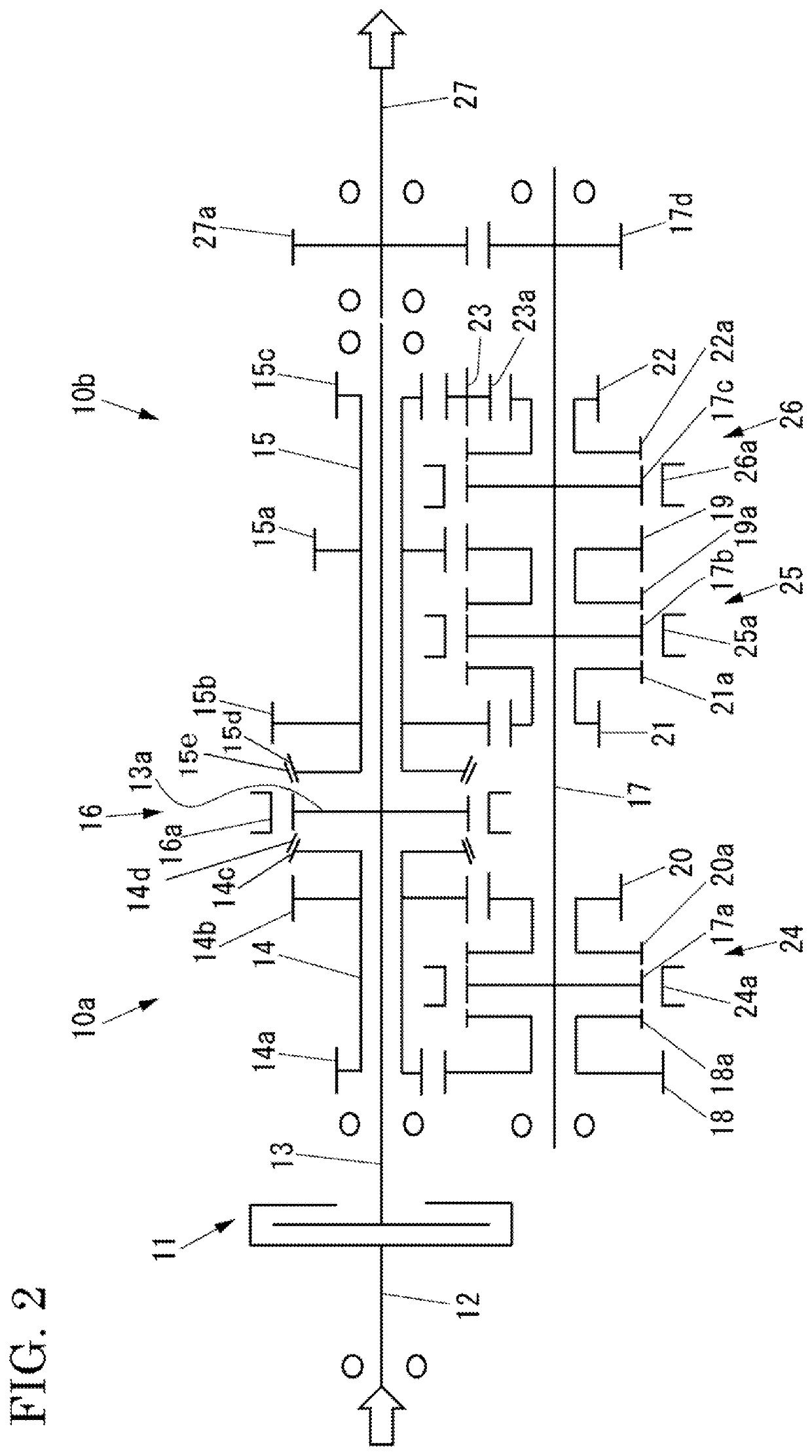
[0079]As described above, the parallel axis type transmission of the first embodiment has the following advantages.

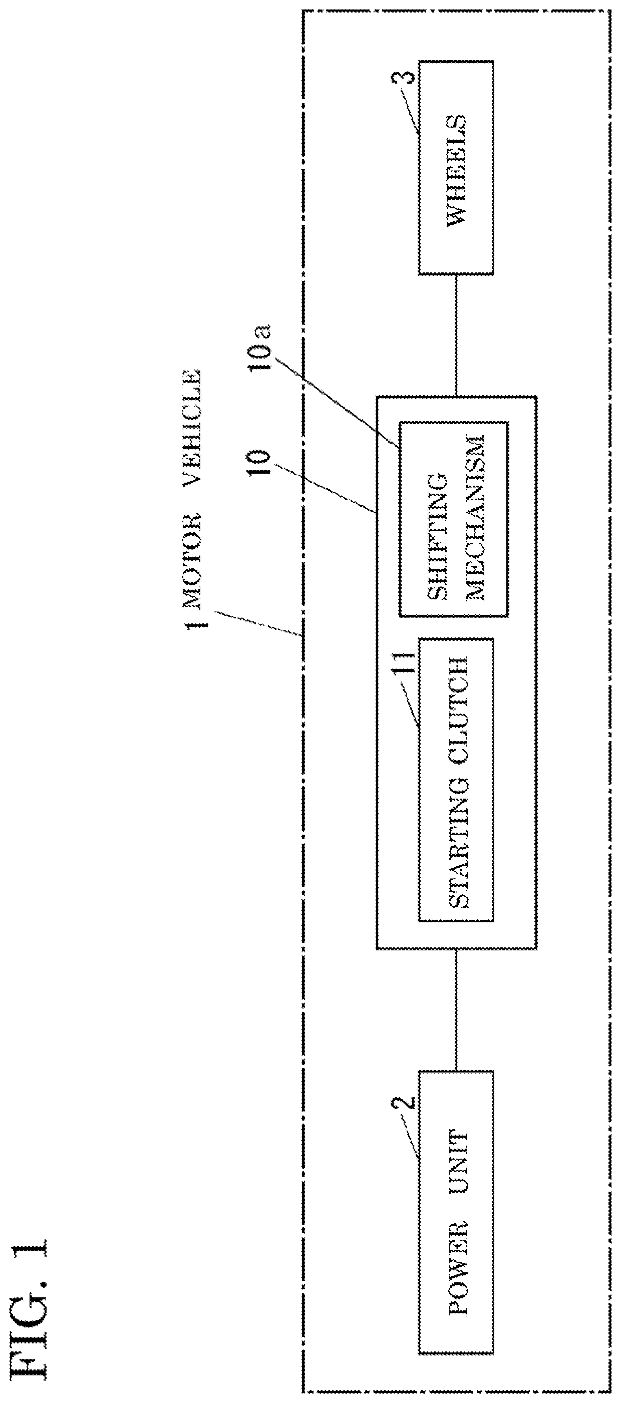
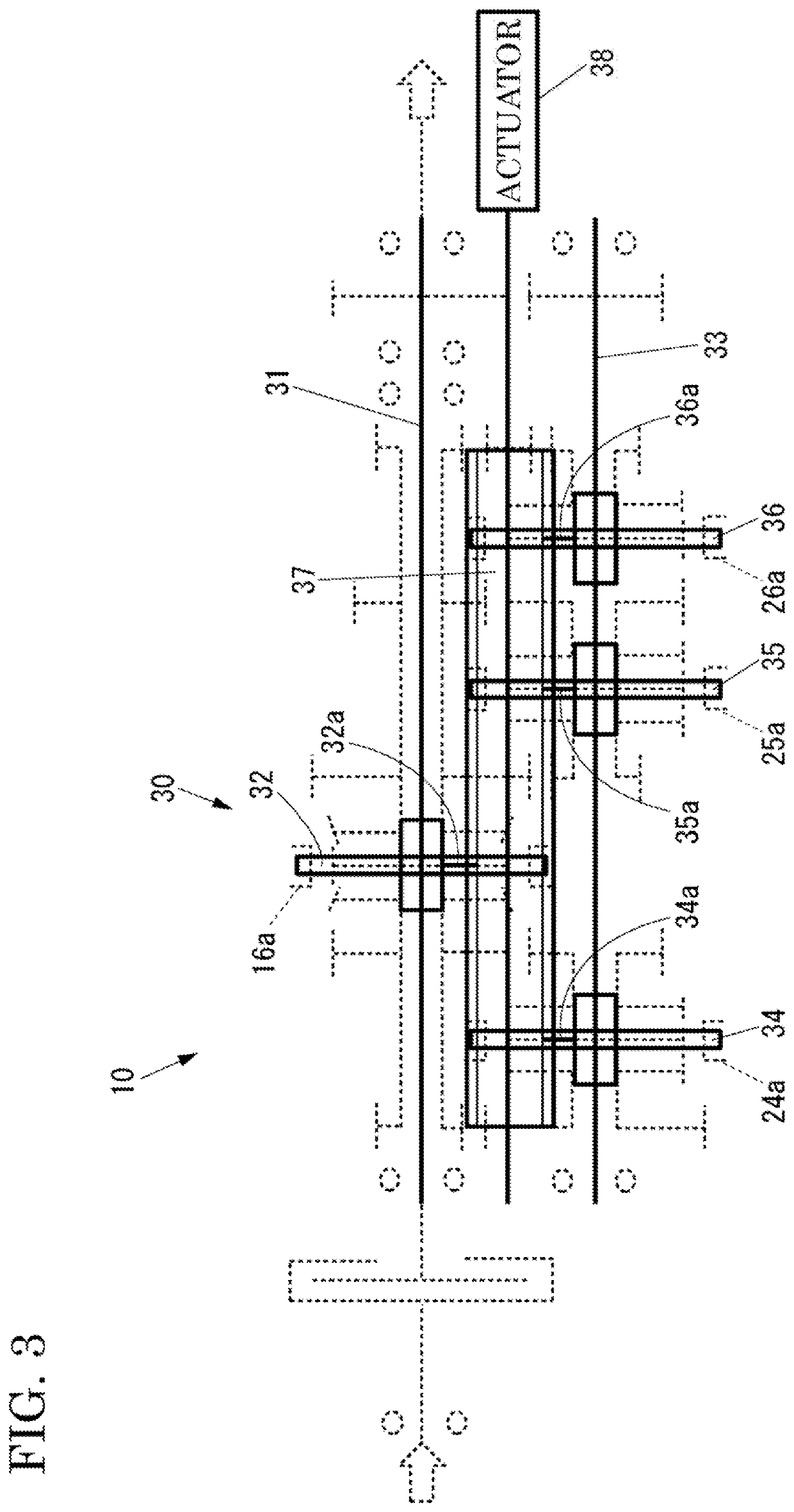
[0080]The path shifting part 16 is arranged between the first power transmitting path 10a and the second power transmitting path 10b. Therefore, the transmission provides a great choice of layout plans of the transmissions, and the operation system 30 can be collectively and easily arranged.

[0081]The path shifting part 16 employs the synchro-mesh type mechanism. Therefore, its diameter can be smaller to decrease its moment of inertia, and it does not necessary for provide the power for its engagement while it is activated. Due to this reason, the transmission can be compact and light in weight.

[0082]The path shifting part 16 can be shifted after the dog clutch gear 18a, (or 22a, 20a, 21a) of the next on-coining gear is engaged with its shift sleeve 24a (or 25a), and accordingly the gear changing can be accomplished in a very short time. Therefore, the starting clutch 11...

second embodiment

[0088]Next, a transmission of a second embodiment according to the present invention will be described below.

[0089]FIG. 7 shows an FR 5-speed parallel axis type transmission of the second embodiment. The input shaft 13 further has a dog clutch gear 13b with a not-shown cone portion next to the dog clutch 13b. The output shaft 27 further has a hub portion27b with splines on its radially outer side. A third shift sleeve 42a is always engaged with the hub portion 27b, and it is selectively engaged with the dog clutch gear 13b. A synchronizer ring 13c is arranged between the dog clutch gear 13b and the hub portion 27b. The third shift sleeve 42a, the synchronizer ring 13c, the hub portion 27b, the cone portion and the dog clutch gear 13b correspond to a third power shifting part 42 of the present invention. The other parts and portions are similar to those in the first embodiment.

[0090]The paths to obtain the first speed, the third speed, and the fifth speed correspond to the first powe...

third embodiment

[0098]Next, a transmission of a third embodiment according to the present invention will be described below.

[0099]FIG. 8 is an FR 8-speed parallel axis type transmission of the third embodiment. This transmission 10 is obtained by adding other power shifting parts to that of the first embodiment.

[0100]A first counter shaft 17, corresponding to the counter shaft 17 of the first embodiment, is arranged parallel to the input shaft 13. A second counter shaft 43 is arranged parallel to the input shaft 13 and the first counter shaft 17.

[0101]A fifth driven gear 44 is always engaged with the first drive gear 14a. The fifth driven gear 44 is formed with a dog clutch gear 44a as one unit, and they are freely rotatable on the second counter shaft 43.

[0102]A seventh driven gear 46 is always engaged with the third drive gear 14b. The seventh driven gear 46 is formed with a dog clutch gear 46a as one unit, and they are freely rotatable on the second counter shaft 43.

[0103]The first drive gear 14...


PUM


Abstract

A transmission includes a first power transmitting path of gears that obtains odd number speeds and has an output part, a second power transmitting path of gears that obtains even number speeds and has an output part; a first gear shifting part incorporated in the first power transmitting path to obtain one of the odd number speeds, a second gear shafting part incorporated in the second power transmitting path to obtain one of the even number speeds, and a path shifting part that is arranged between the first and second power transmitting parts. The path shifting part shifts the first second power transmitting paths to output power to the output shaft.

Description

BACKGROUND OF THE INVENTION1. Field of the Invention[0001]The present invention relates to a parallel axis type transmission which is mounted on a motor vehicle to propel the motor vehicle.2. Description of the Related Art[0002]Conventional parallel axis type transmissions are disclosed in Japanese Unexamined Patent Applications Publication No. 2007-534899, 2008-544161, and 2010-196745. These conventional transmissions include two shifting clutches and two power transmitting path systems. The two power transmitting paths consist of first sets of gears to obtain odd number speeds and second sets of gears to obtain even number speeds. The two power transmitting paths are alternately changed to be shifted by the two shifting clutches. This is, what is called, a dual clutch transmission (DCT).[0003]The above known conventional parallel axis type transmissions, however, encounter a problem in that there are poor choices of layout plans of the parallel axis transmissions because one of th...

Claims


Application Information

Patent Timeline
Patent Type & Authority Patents(United States)
IPC IPC(8): F16H3/00F16H3/093F16H61/04F16H3/08F16H3/091
CPCF16H61/0403F16H3/091F16H3/0915F16H3/093F16H3/006F16H3/08F16H2003/0933F16H2003/0811F16D23/06F16H3/12F16H2200/006F16H2200/0043F16H2200/0047
Inventor HORIGUCHI, HIROTAKATAKAHASHI, KOTEIYAGI, RYO
Owner KYOWA METAL WORKS
Why Eureka
Try Eureka