Vehicle brake device

A technology for braking devices and vehicles, which is applied to braking transmission devices, braking action starting devices, brakes, etc., can solve the problems of large-scale solenoid valves, increased manufacturing costs, and increased differential pressure resistance of solenoid valves.

Active Publication Date: 2022-04-29
ADVICS CO LTD
View PDF7 Cites 0 Cited by
  • Summary
  • Abstract
  • Description
  • Claims
  • Application Information

AI Technical Summary

Problems solved by technology

However, increasing the differential pressure resistance of the solenoid valve requires an increase in the size of the solenoid valve, which leads to an increase in the size of the device
In addition, the development of a dedicated solenoid valve also increases the manufacturing cost

Method used


Image

  • Vehicle brake device
  • Vehicle brake device
  • Vehicle brake device

Examples


Embodiment Construction

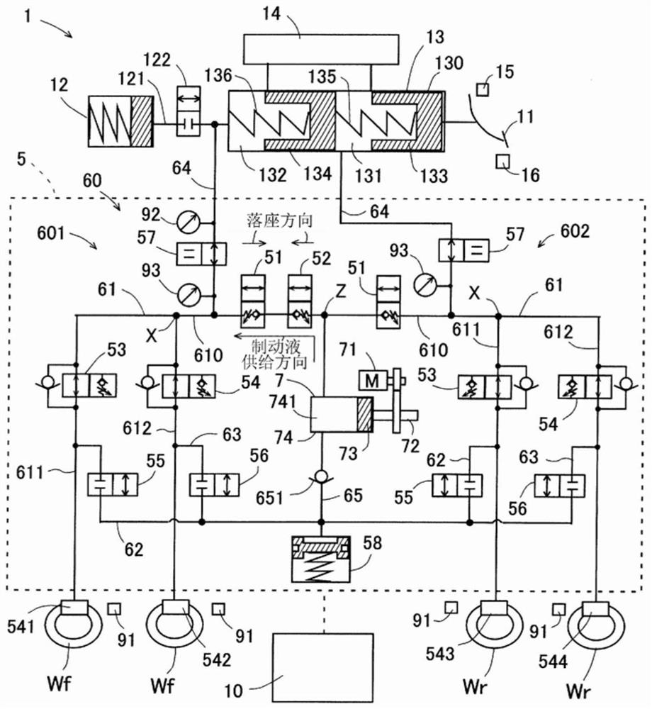
[0014] Hereinafter, embodiments of the present invention will be described based on the drawings. In addition, each drawing used for description is a schematic diagram. The vehicle brake device 1 of the present embodiment includes a brake pedal 11 , a stroke simulator 12 , a master cylinder unit 13 , a reservoir 14 , a brake switch 15 , a stroke sensor 16 , an actuator 5 , and a brake ECU 10 .

[0015] The brake pedal 11 is an operation member that enables the driver to perform a brake operation. The brake switch 15 is a sensor that detects whether or not the brake pedal 11 is operated. The stroke sensor 16 is a sensor that detects the pedal stroke (hereinafter referred to as “stroke”) of the brake pedal 11 . The brake switch 15 and the stroke sensor 16 output detection signals to the brake ECU 10 .

[0016] The stroke simulator 12 is a device that generates a reaction force corresponding to the operation of the brake pedal 11 . Stroke simulator 12 is connected to master c...


PUM


Abstract

The present invention is provided with: a first supply device (7) for supplying brake fluid to wheel cylinders (541, 542); a first supply path (61) connecting the first supply device (7) and the wheel cylinders (541, 542); and a first solenoid valve (51) and a second solenoid valve (52) provided in the first supply path (61), the first solenoid valve (51) being disposed in the first supply path (61) such that the seating direction, which is the direction in which the valve body (81) is seated on the valve seat (82), is opposite to the brake fluid supply direction, which is the direction in which the brake fluid is supplied from the first supply device (7) toward the wheel cylinders (541, 542) in the first supply path (61). The second solenoid valve (52) is disposed in the first supply path (61) such that the seating direction is the same as the brake fluid supply direction.

Description

technical field [0001] The present invention relates to a brake device for a vehicle. Background technique [0002] The brake device for a vehicle includes, for example: a supply device that supplies brake fluid to a connection destination; a supply path that connects the supply device and the first wheel cylinder; a normally closed solenoid valve that is provided in the supply path; and a control unit that controls Supply device and solenoid valve. The controller operates the supply device to open the solenoid valve to supply the brake fluid to the first wheel cylinder, and the hydraulic pressure (wheel pressure) of the first wheel cylinder increases to increase the braking force. Such a vehicle braking device is described in, for example, US Patent No. 10189456 . [0003] Patent Document 1: Specification of US Patent No. 10189456 [0004] Here, when it is intended to stop the flow of brake fluid from the first wheel cylinder to the supply device, the solenoid valve is c...

Claims


Application Information

Patent Timeline
Patent Type & Authority Applications(China)
IPC IPC(8): B60T13/138B60T8/17B60T13/68B60T17/18B60T8/42
CPCB60T13/148B60T8/17B60T13/686B60T17/18B60T8/42B60T13/745B60T13/146B60T8/4081B60T13/662B60T7/042B60T17/22B60T8/94B60T2270/402B60T2270/406B60T2270/88
Inventor 坂田康典草野彰仁
Owner ADVICS CO LTD
Why Eureka
Try Eureka