
Monitoring an absorption rate of inductively coupled coils

a technology of inductively coupled coils and absorption rates, which is applied in the direction of instruments, magnitude/direction of magnetic fields, and measurement using magnetic resonance, etc., can solve the problems of inadmissible high local concentration of hf energy, burns may occur, and heat of body tissue, etc., and achieves relatively easy, easy and precise determination.

Active Publication Date: 2020-10-13
SIEMENS HEALTHCARE GMBH
View PDF16 Cites 0 Cited by
  • Summary
  • Abstract
  • Description
  • Claims
  • Application Information

AI Technical Summary

Benefits of technology

The patent is about a way to monitor the rate at which a magnetic field absorbs into a coil. This method helps to determine the actual strength of the magnetic field, which helps to avoid unnecessary output losses and ensures accurate transmission of power. By measuring the power and current in the primary coil, the absorbed power can be easily calculated. An adjustment scan can also be carried out to determine the ratio of the actual magnetic field strength to the transmission power. This ratio can then be used to accurately determine the strength of the magnetic field during the examination. A computer program product is also described to carry out the monitoring method efficiently. Overall, the patent provides a simple and effective way to accurately monitor the absorption rate of magnetic coils.

Problems solved by technology

The absorption of HF energy may lead to heating of the body tissue.
Burns may occur with inadmissibly high local concentration of HF energy.

Method used


Image

  • Monitoring an absorption rate of inductively coupled coils
  • Monitoring an absorption rate of inductively coupled coils
  • Monitoring an absorption rate of inductively coupled coils

Examples


Embodiment Construction

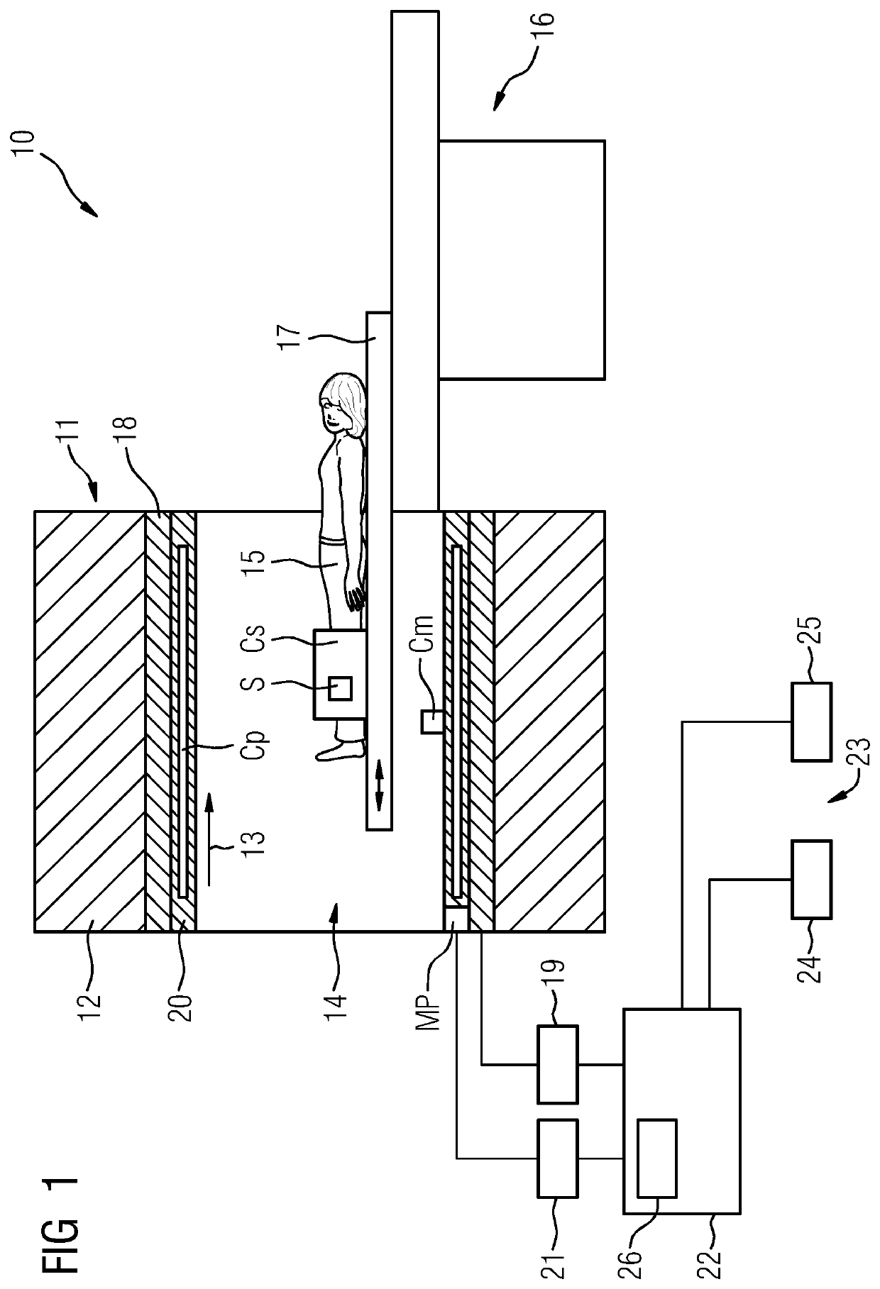
[0043]FIG. 1 schematically depicts a magnetic resonance device 10. The magnetic resonance device 10 includes a magnetic unit 11 having, for example, a superconductive, main magnet 12 for generating a strong and, in particular, time-constant B0 main magnetic field 14. Furthermore, the magnetic resonance device 10 includes a patient recording region 14 for recording a patient 15. In the present exemplary embodiment, the patient recording region 14 is cylindrical and cylindrically surrounded in a circumferential direction by the magnetic unit 11. Basically, a design of the patient recording region 14 that differs herefrom is also conceivable. The patient 15 may be variably positioned in the patient recording region 14 by a patient positioning device 16 of the magnetic resonance device 10 depending on the examination region. The patient positioning device 16 has for this purpose a patient couch 17 designed so it may move inside the patient recording region 14.

[0044]The magnetic unit 11 ...


PUM

PropertyMeasurementUnit
field strengthaaaaaaaaaa
B1 field strengthaaaaaaaaaa
Magnetic Resonance Imagingaaaaaaaaaa

Abstract

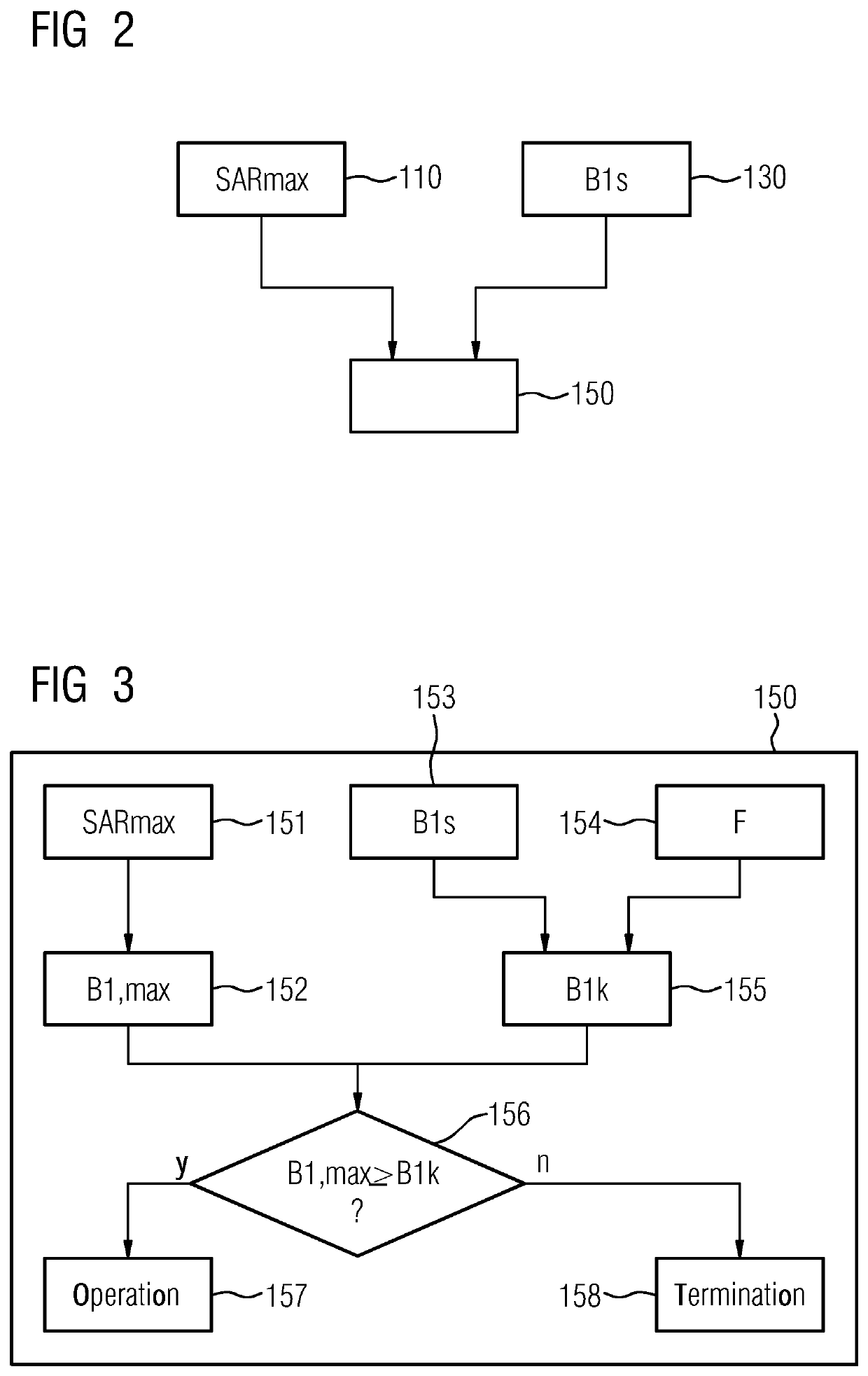
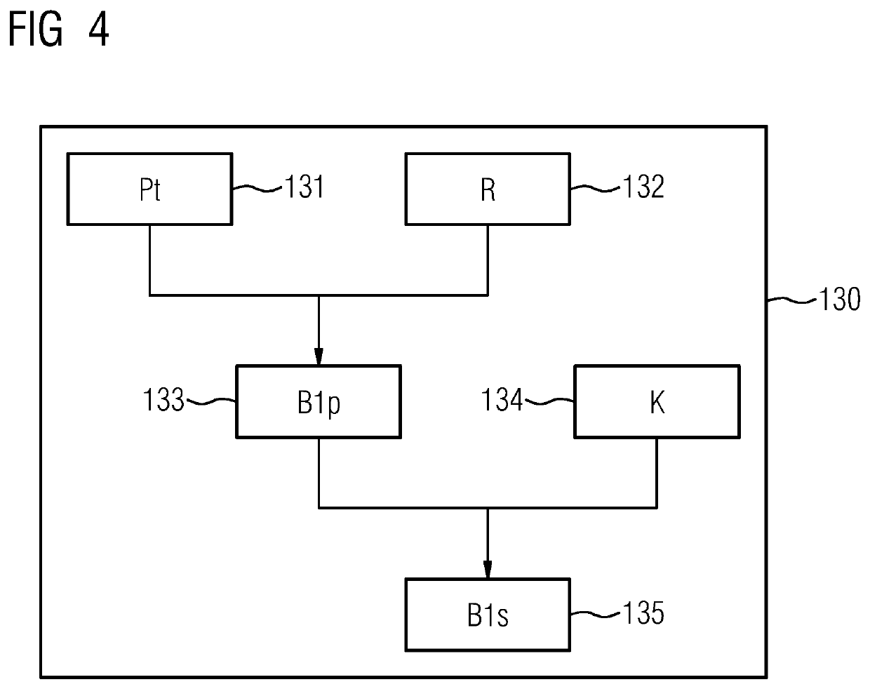
The disclosure relates to a method for monitoring an absorption rate when using a primary coil of a magnetic resonance device and a secondary coil inductively coupled to the primary coil and to a monitoring unit, a magnetic resonance device and a computer program product. According to the method a maximum admissible absorption rate is provided, using which a maximum admissible B1 field strength of the secondary coil is determined. Furthermore, an actual B1 field strength of the secondary coil is determined. The absorption rate is monitored using the actual B1 field strength of the secondary coil and the maximum admissible B1 field strength of the secondary coil.

Description

[0001]The application claims the benefit of German Patent Application No. DE 10 2016 209 088.7, filed May 25, 2016, incorporated by reference in its entirety.TECHNICAL FIELD[0002]The disclosure relates to a method for monitoring an absorption rate when using a primary coil of a magnetic resonance device and a secondary coil, to a monitoring unit, to a magnetic resonance device, and to a computer program product.BACKGROUND[0003]Magnetic Resonance Imaging (MRI) is a known technique for generating images of the inside of the body of an examination object, which is based on the physical phenomenon of magnetic resonance (MR). For this purpose, fast-switched gradient pulses may be overlaid on a static main magnetic field B0 during a magnetic resonance examination in a magnetic resonance device. It is possible to trigger magnetic resonance signals by irradiating a high-frequency (HF) magnetic alternating field B1, (e.g., in the form of HF pulses), into the examination object. The energy of...

Claims


Application Information

Patent Timeline
Patent Type & Authority Patents(United States)
IPC IPC(8): G01R33/28G01R33/36G01R33/48G01R33/24G01R33/34
CPCG01R33/3642G01R33/288G01R33/48G01R33/246G01R33/34076
Inventor BIELMEIER, WOLFGANGBRINKER, GERHARDNISTLER, JÜRGENSCHNETTER, VOLKER
Owner SIEMENS HEALTHCARE GMBH
Learn More