
Enhanced mobility wheelchair

a mobility wheelchair and wheelchair technology, applied in the field of enhanced mobility wheelchairs, can solve the problems of inconvenient forward ascending and aft descending of even small steps, inconvenient use of wheelchair users, and inability to properly load stairs by resting on stair treads of larger diameter wheels and tracks

Active Publication Date: 2020-10-20
COX KENNETH RAY
View PDF16 Cites 10 Cited by
  • Summary
  • Abstract
  • Description
  • Claims
  • Application Information

AI Technical Summary

Benefits of technology

The patent describes a system for controlling the speed and position of a skid system, such as a wheelchair. The system uses pitch and roll factors to adjust the speed of the skid system based on its current position and any deviation from the desired target. This allows for smoother operation of the skid system and provides the occupant with more time to react to any tilt or deviation in their position. The system can also adjust the speed of travel to match the desired target, or stop the movement of the wheelchair in certain situations. Overall, this system enhances the overall safety and efficiency of wheelchair operations.

Problems solved by technology

While U.S. Pat. No. 6,484,829 is well suited for aft climbing and forward descending of multiple height steps and stairs, it is not suitable for forward ascending and aft descending of even small steps.
Turning around to negotiate low height steps would be a hindrance that would not be tolerated by wheelchair occupants.
Large diameter wheels are well suited for single low height steps, but larger diameter wheels and tracks do not properly load stairs by resting on stair treads.
While large diameter wheels and tracks have been shown to climb stairs, they require high friction to grab step edges.
Inadequate coefficient of friction can result in a stair-climbing device sliding down the stairs.
The means for monitoring cam angles had several issues, including adjustment slipping, failure to hold the lower cam tips off the ground, lack of absolute angle measurement and large volume required to house it.

Method used


Image

  • Enhanced mobility wheelchair
  • Enhanced mobility wheelchair
  • Enhanced mobility wheelchair

Examples


Embodiment Construction

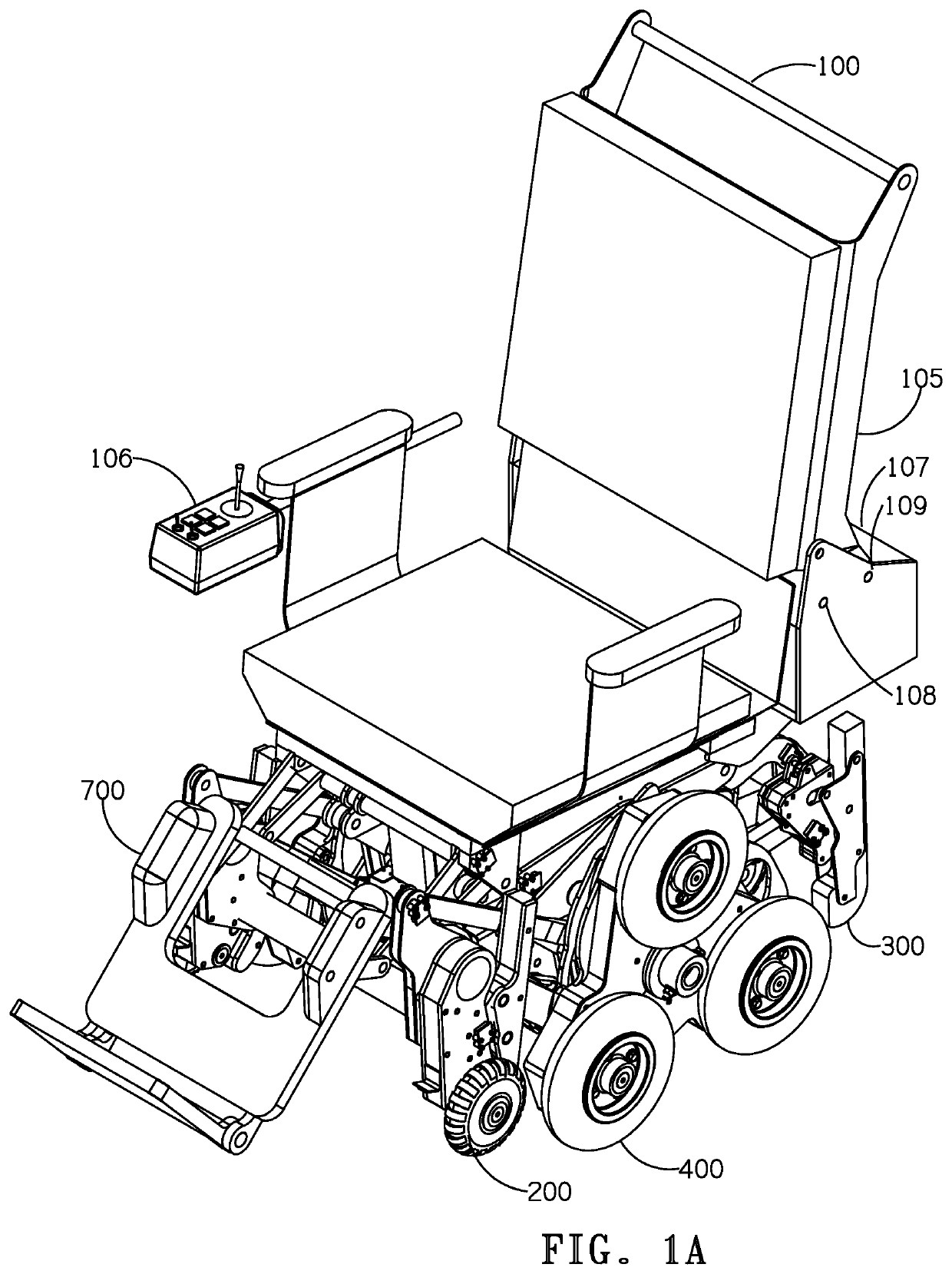
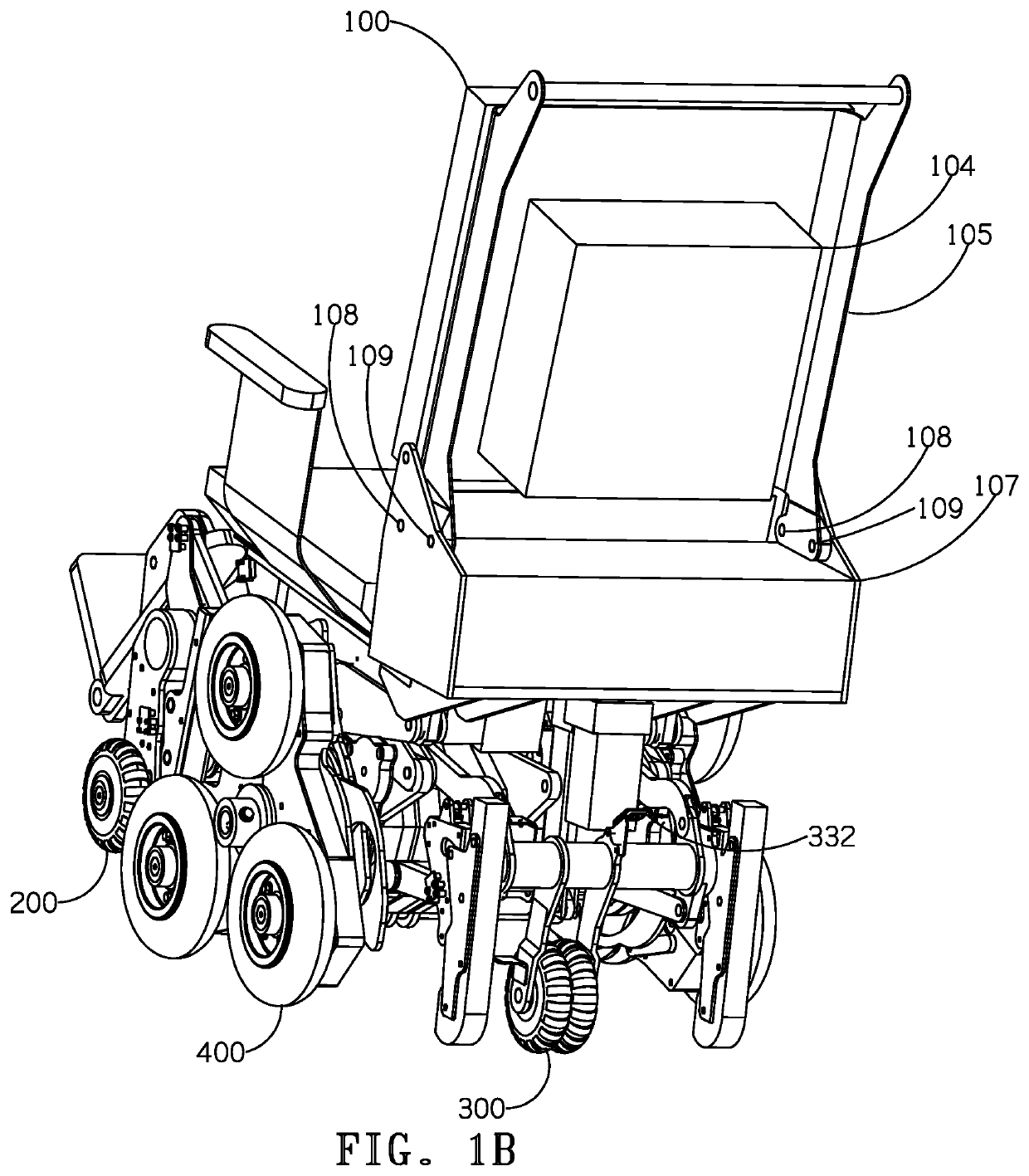
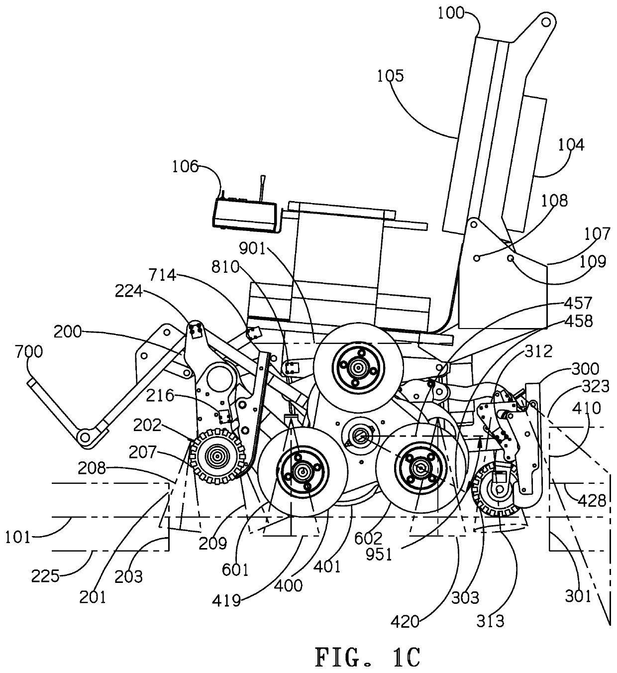
[0006]For this invention, down steps in the direction that the wheelchair faces, such as for aft ascending and forward descending are defined as forward down steps, FDS. Up steps in the direction the wheelchair faces, such as for forward ascending and aft descending steps are defined as forward up steps, FUS. Climbing refers to either ascending or descending. The front balancing means or skid system 200 includes articulated skid runners 204 and balancing wheels, or skid wheels 207 and is named the skid system 200 and is shown in FIG. 3A. Multi-directional skid wheels are preferred for their reduce lateral operating width although they could be castering type wheels. The rear balancing means or caster system 300 includes the function of a castering wheel but also includes caster runners 319 and is named the caster system 300 and is shown in FIG. 5A. Multi-directional wheels are well known wheels such as those manufactured by Rotacaster of Australia. They provide the function of caste...


PUM


Abstract

An enhanced mobility wheelchair with semi-autonomous control logic includes criteria for selecting level, stair, and slope modes. Each mode progresses through criteria-invoked phases as the wheelchair travels. Each axis performs an assigned duty for each mode and phase combination to seek a defined target. Control logic invokes stair mode from the level mode when steps are sensed. Criteria restricts negotiating obstacle angles and heights encountered beyond capability and permits reversed travel to exit obstacle. Front and rear support systems include the ability to sense both forward and backward facing steps by adding distance sensors, sensing linkage and rotary sensors. Legrest adjustment raises the feet for forward step climbing and shortens the wheelchair length for tight turns. Steep down slope and steep up slope modes are invoked from a small angle slope mode. Absolute measurement of spider rotation and spider cam engagement does not require adjustment.

Description

CROSS-REFERENCE TO RELATED APPLICATION[0001]It is an object of this invention to define improvements over the previously patented construction by this inventor (U.S. Pat. No. 6,484,829) entitled “BATTERY POWERED STAIR-CLIMBING WHEELCHAIR” with these new designs offering semi-autonomous control logic with criteria for selecting level, stair, and slope modes, phases for each mode, duties for each axis and command values for each axis to seek target values. A further improvement is means to forward-ascend and backward-descend low height steps, adjust seat height, and adjust legrest while improving the capacity to back up high steps and climb stairs, as well as provide improved sensing spider crowd engagement of steps and stairs. A further improvement is the ability to approach operational stair angle, step height, and slope angle limits and reverse direction to avoid exceeding the operational limits. While this invention is primarily intended for use as a wheelchair for carrying occupa...

Claims


Application Information

Patent Timeline
Patent Type & Authority Patents(United States)
IPC IPC(8): A61G5/06A61G5/04A61G5/10A61G5/12A61G5/08B60K26/02
CPCA61G5/08A61G5/1067A61G5/1059A61G5/046A61G5/061A61G5/128A61G5/127B60K26/02B60K2026/029A61G5/065A61G5/1032A61G2203/14A61G5/1089A61G5/125B60K1/00B60K2001/001B60Y2200/84
Inventor COX, KENNETH RAY
Owner COX KENNETH RAY
Learn More