Wind turbine system with time distributed transitions

a wind turbine and transition technology, applied in the direction of engine control parameters, engine fuction, control multiple engines simultaneously, etc., can solve the problem and achieve the effect of reducing the life of the wind turbine system

Active Publication Date: 2020-10-20
VESTAS WIND SYST AS
View PDF19 Cites 3 Cited by
  • Summary
  • Abstract
  • Description
  • Claims
  • Application Information

AI Technical Summary

Benefits of technology

[0005]It may be seen as an object of the present invention to provide a wind turbine system that solves the above mentioned problems with structural load exerted by the wind turbine modules and the reduction in life time of the wind turbine system.
[0011]The invention is particularly, but not exclusively, advantageous for obtaining a wind turbine system which may enable reducing the structural load, such as the maximum structural load (which may be referred to as peak structural load), exerted by the wind turbine modules during transitions between system operational states and / or which may enable increasing the lifetime of the wind turbine system.
[0012]The peak structural load exerted by the wind turbine modules during transitions between system operational states entails demanding requirements on the support structure and reduces lifetime of the wind turbine system. It is an advantage of embodiments of the present invention that this peak structural load can be reduced by arranging the wind turbine module transitions so that the plurality of wind turbine module transitions are distributed in time with respect to each other. By having the wind turbine module transitions so that the plurality of wind turbine module transitions are distributed in time with respect to each other, it is avoided that they are all co-incident in time and instead they become distributed in time, which in turn entails that the structural loads associated with the plurality of wind turbine module transitions become distributed in time. In other words, the wind turbine module transitions within the plurality of wind turbine module transitions are distributed in time with respect to each other so that a maximum wind turbine system transition generated structural load on the support structure is reduced with respect to a wind turbine system transition with the plurality of wind turbine module transitions being simultaneous.

Problems solved by technology

The peak structural load exerted by the wind turbine modules during transitions between system operational states entails demanding requirements on the support structure and reduces lifetime of the wind turbine system.

Method used


Image

  • Wind turbine system with time distributed transitions
  • Wind turbine system with time distributed transitions
  • Wind turbine system with time distributed transitions

Examples


Embodiment Construction

[0028]The present invention will now be explained in further details. While the invention is susceptible to various modifications and alternative forms, specific embodiments have been disclosed by way of examples. It should be understood, however, that the invention is not intended to be limited to the particular forms disclosed. Rather, the invention is to cover all modifications, equivalents, and alternatives falling within the spirit and scope of the invention as defined by the appended claims.

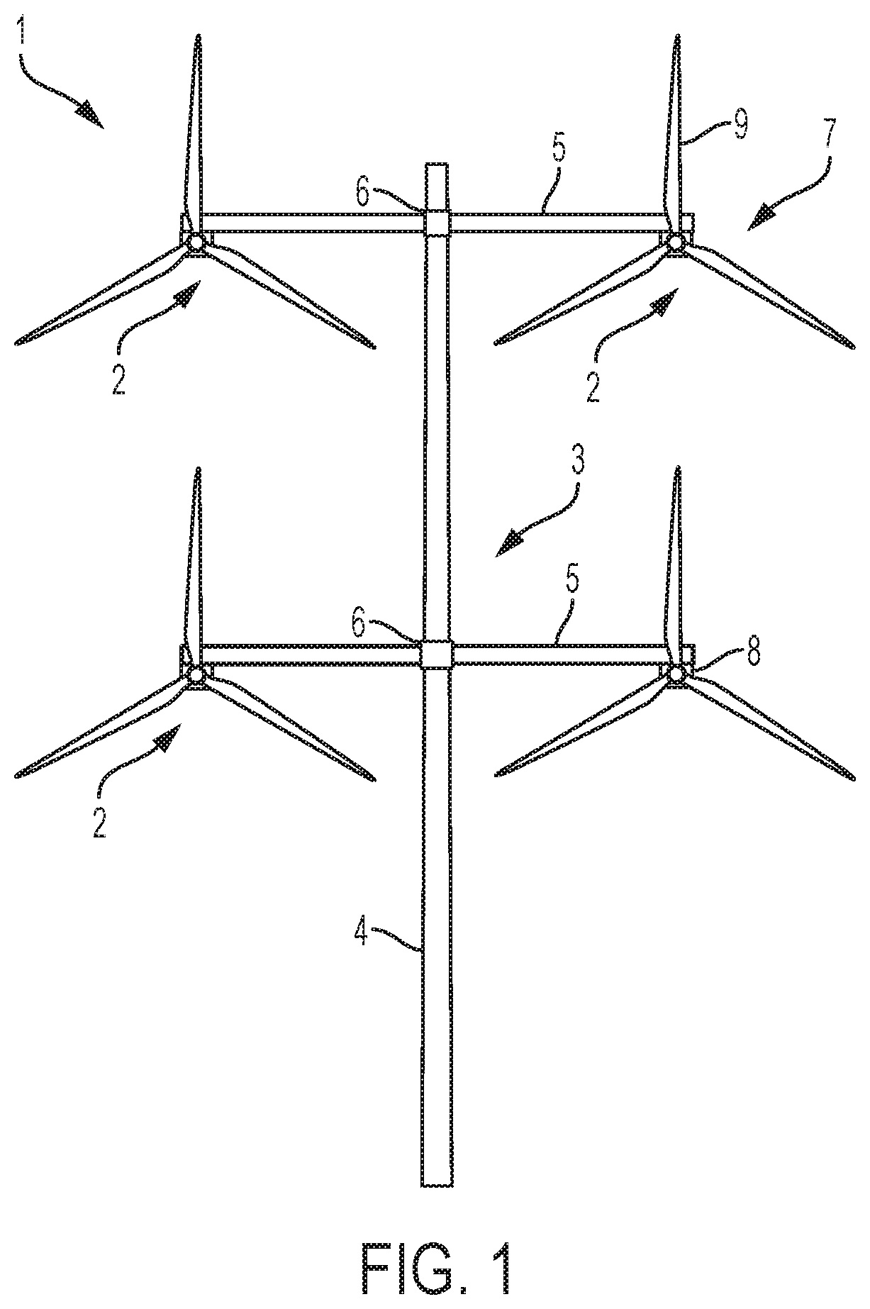
[0029]FIG. 1 depicts a wind turbine system 1, wherein the wind turbine system is comprising:[0030]A support structure 3 including a tower 4 and arms 5 mounted to the tower 4 at junctions 6,[0031]a plurality of wind turbine modules 2 mounted to the support structure 3 wherein each of the plurality of wind turbine modules comprises a rotor 7 with blades 9.

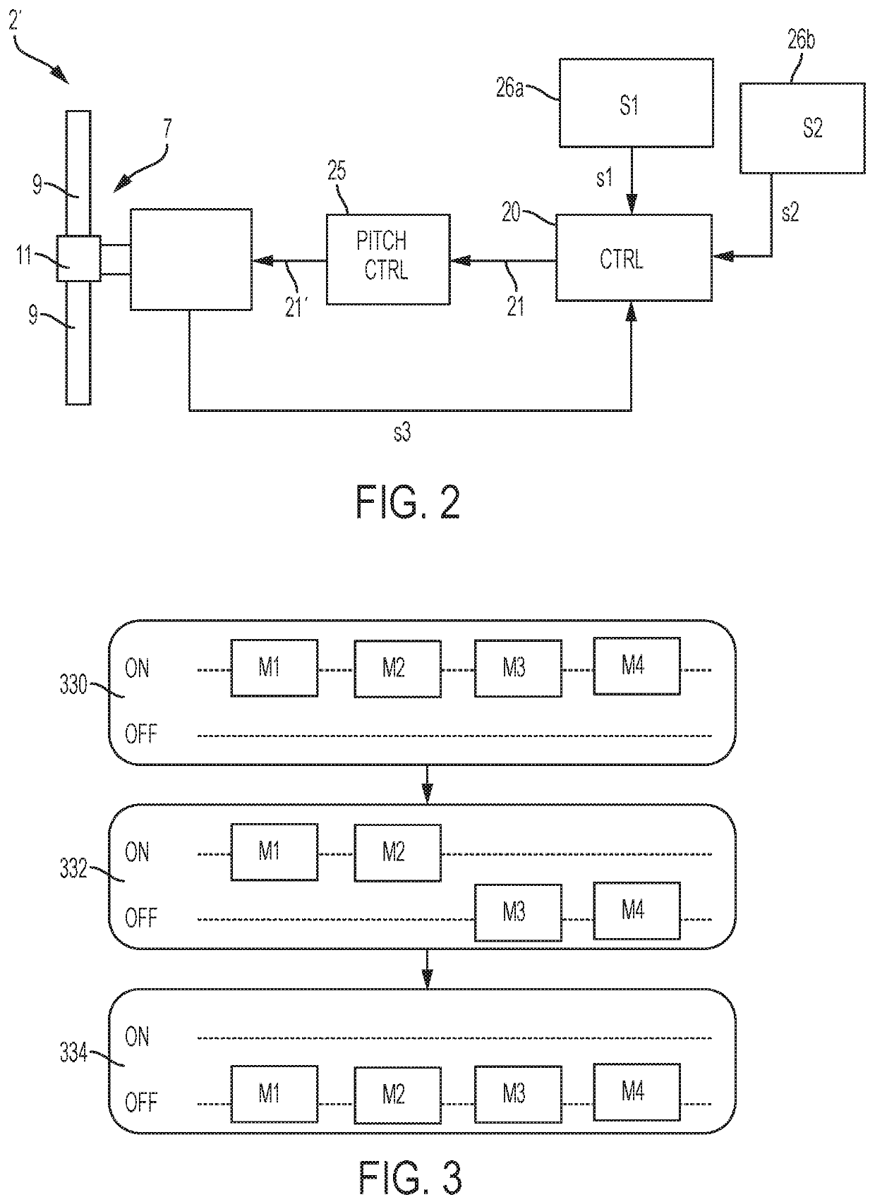
[0032]The wind turbine system further comprises a control system 20 as shown in FIG. 2. The control system 20 is arranged to execute a wind...


PUM


Abstract

There is presented a wind turbine system, wherein the wind turbine system is comprising a support structure, a plurality of wind turbine modules mounted to the support structure wherein each of the plurality of wind turbine modules comprises a rotor, and wherein the wind turbine system further comprises a control system, wherein the control is arranged to execute a wind turbine system transition from a first system operational state of the wind turbine system to a second system operational state of the wind turbine system, and wherein the wind turbine system transition is performed by executing a plurality of wind turbine module transitions from a first module operational state of a wind turbine module to a second module operational state of the wind turbine module wherein the plurality of wind turbine module transitions are distributed in time with respect to each other.

Description

FIELD OF THE INVENTION[0001]The present invention relates to a wind turbine system, more particularly a wind turbine system with a plurality of wind turbine modules wherein the plurality of wind turbine module may change operational state at different points in time with respect to each other and a corresponding method, computer program product and control system.BACKGROUND OF THE INVENTION[0002]A wind turbine system with a plurality of wind turbine modules mounted to a support structure may be subjected to a significant structural load exerted by the wind turbine modules, in particular during transitions between system operational states, which significant structural loads may reduce the lifetime of the wind turbine system.[0003]Hence, an improved wind turbine system would be advantageous, and in particular a wind turbine system enabling reducing the structural load exerted by the wind turbine modules and / or enabling increasing the lifetime of the wind turbine system.[0004]GB 24438...

Claims


Application Information

Patent Timeline
Patent Type & Authority Patents(United States)
IPC IPC(8): F03D7/02F03D7/04F03D1/02
CPCF03D7/0264F03D7/026F03D7/0296F03D1/02F03D7/0224F03D7/042F05B2260/90F05B2270/111F05B2270/335F05B2270/32F05B2270/1095F05B2270/327F05B2260/74F05B2270/328F05B2260/85Y02E10/72
Inventor MIRANDA, ERIK CARL LEHNSKOVGRUNNET, JACOB DELEURANCASTAIGNET, DAMIEN
Owner VESTAS WIND SYST AS
Why Eureka
Try Eureka