
Speaker with dual diffuser

a dual-diffuser, speaker technology, applied in the direction of electrical transducers, frequency/directions obtaining arrangements, enclosures of speakers that attempt to minimize sound distortion, etc., can solve the problems of low efficiency of often under 5%, waste of vibration, and high cost of speaker enclosures, so as to improve both sound quality and energy efficiency. , the effect of improving energy efficiency

Active Publication Date: 2020-10-20
DINABURG TECH CORP
View PDF15 Cites 0 Cited by
  • Summary
  • Abstract
  • Description
  • Claims
  • Application Information

AI Technical Summary

Benefits of technology

This patent describes an improved acoustic loudspeaker that can improve sound quality and energy efficiency compared to previous speakers. It achieves this by using a special design that allows for the movement of air between components, which reduces distortion and short circuits. This design also allows for the output of a larger range of frequencies without the need for additional components. The main technical effects of this patent are improved sound quality and energy efficiency in an acoustic loudspeaker.

Problems solved by technology

Acoustic short circuit refers to sound distortion and cancellation that occurs when sounds waves collide and / or are absorbed by other speaker components such as the enclosure which results in wasteful vibrations.
Unfortunately, speaker enclosures that attempt to minimize sound distortions are often heavy and expensive, and results in very low efficiency of often under 5%, as a substantial portion of the sound energy is cancelled and / or converted to vibration.
The low level of efficiency requires a much greater amount of energy in proportion to the actual sound produced which is wasteful and adds cost to the operation and maintenance of the speaker.

Method used


Image

  • Speaker with dual diffuser
  • Speaker with dual diffuser
  • Speaker with dual diffuser

Examples


Embodiment Construction

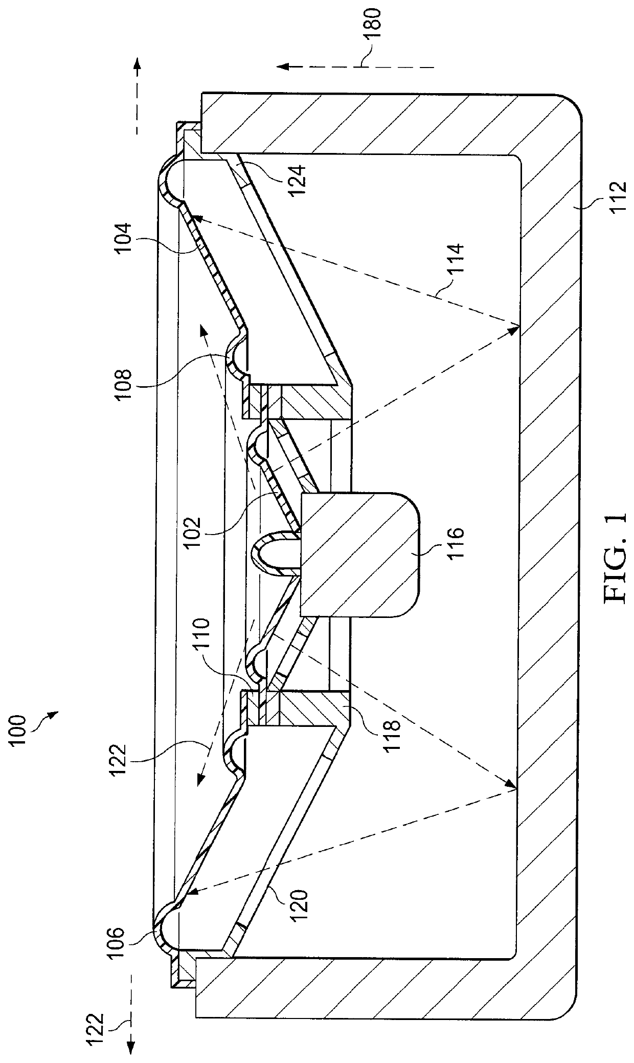
[0019]Referring first to FIG. 1, an exemplary acoustic speaker 100 is illustrated via a top-down cross-sectional view. As shown, the speaker 100 includes a speaker driver 116, a speaker enclosure 112, and a diaphragm (cone) having an inner (active) portion 102 and an outer (stabilizing) portion 104. Both the inner portion and outer portions may be shaped as an annulus (ring) having a desired width. Hinges 108 may separate the inner portion from the outer portion so that the portions may move relative to each other as the inner portion is driven back and forth via the driver that contains at least one electromagnet. The outer edge of the inner portion is approximately the same diameter as the inner edge of the outer portion, the difference in diameter defined by substantially the hinge mechanism. The outer edge of the outer portion may be affixed to a cradle 120 via a hinge as well so that the outer portion may move relative to the cradle which is typically stationary during operatio...


PUM


Abstract

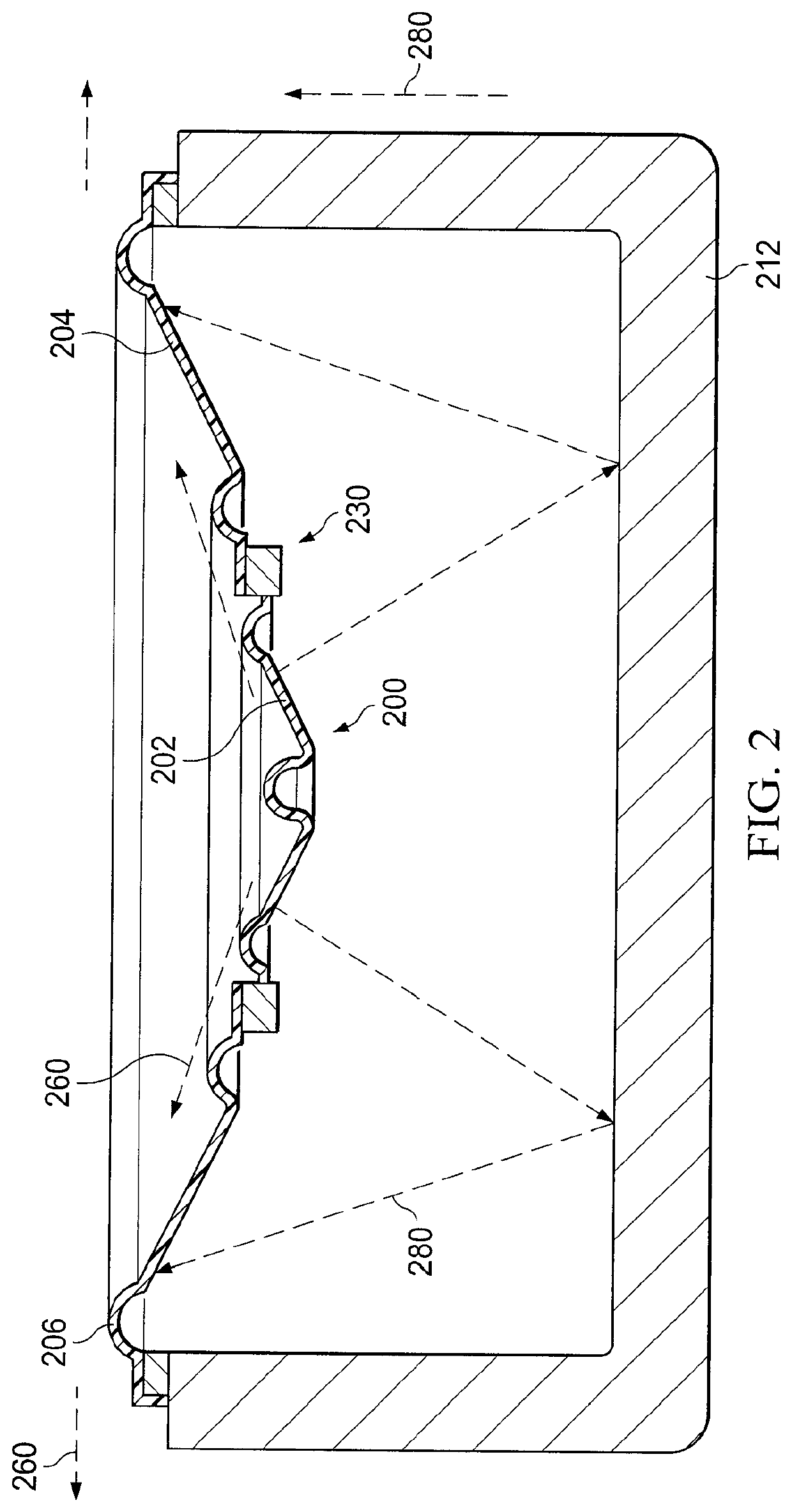
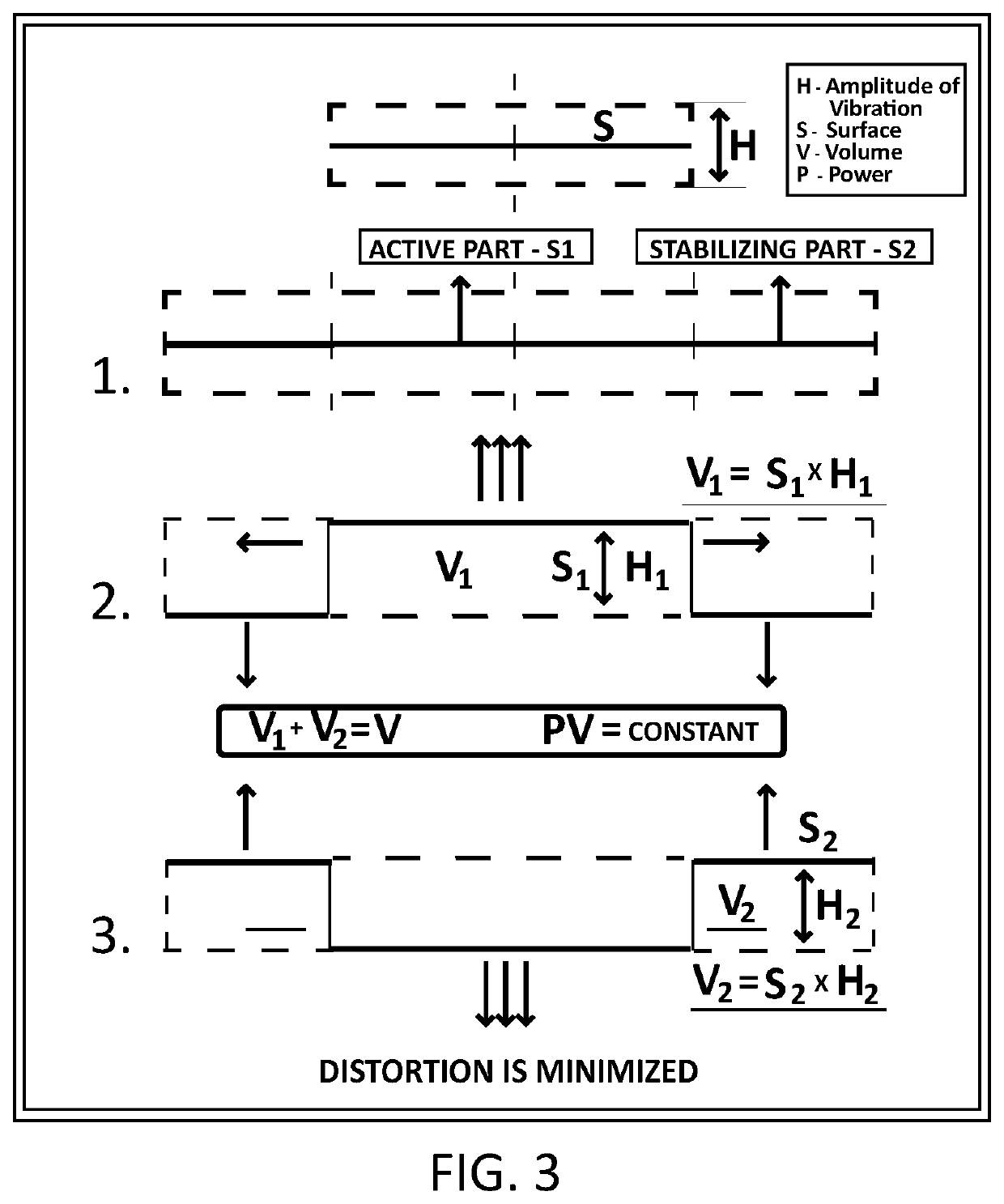
An improved loudspeaker is disclosed. The speaker includes at least one permanent magnet, an electromagnet and a diaphragm. The diaphragm has an inner portion (active portion) and an outer portion (stabilizing portion) that are both typically ring-shaped. The interaction between the magnets causes the inner portion to move back and forth according to the electrical signal inputted. As the inner portion moves forward, the outer portion tends to move backward relative to the inner portion. The movement of the active portion tends to produce corresponding forces on the stabilizing portion that cause the stabilizing portion to move and create sound in a symbiotic fashion. In certain embodiments, the portions move relative to each other as sound is produced so that a relatively constant volume of air is displaced on either side of the diaphragm thus minimizing acoustic distortion. The inner portion may be connected to the outer portion via a hinge and / or flexible material which allows the portions to move relative to each other.

Description

TECHNICAL FIELD[0001]The subject matter described herein relates to audio equipment, and more particularly, to improved speaker technology compared to speakers known in the prior art.BACKGROUND[0002]A conventional loudspeaker (or speaker) is an electroacoustic transducer that converts an electrical signal representing audio into the corresponding sound.[0003]Speakers of the prior art include at least one sound driver for producing sound that is typically housed in an enclosure known as a speaker cabinet / enclosure. Some speakers have more than one driver each of which may produce sounds in a particular frequency range, such as tweeters, mid-range drivers, woofers and so forth. The design and materials used by a speaker enclosure play an important role in the quality of sound produced by the driver(s). Heavy and expensive enclosure cabinets may be incorporated into speaker design in order to mitigate the phenomenon of acoustic short circuit and other issues. Acoustic short circuit ref...

Claims


Application Information

Patent Timeline
Patent Type & Authority Patents(United States)
IPC IPC(8): H04R9/06H04R7/12H04R1/02H04R9/02H04R7/18
CPCH04R7/18H04R7/12H04R9/025H04R1/025H04R9/06H04R7/14H04R1/24
Inventor DINABURG, MIKHAIL
Owner DINABURG TECH CORP
Learn More