Methods and systems for operating a fleet of pumps

a technology for fleets and pumps, applied in the direction of piston pumps, pump parameters, borehole/well accessories, etc., can solve the problems of adding further equipment requirements to the footprint, and further potential employee hazards

Active Publication Date: 2020-10-27
BJ ENERGY SOLUTIONS LLC FORMERLY TES ASSET ACQUISITION LLC
View PDF365 Cites 127 Cited by
  • Summary
  • Abstract
  • Description
  • Claims
  • Application Information

AI Technical Summary

Benefits of technology

[0006]According to one embodiment of the disclosure, a method of operating a plurality of pump units associated with a high-pressure, high-power hydraulic fracturing assembly is provided. Each of the pump units may include a turbine engine, a driveshaft, a gearbox connected to the turbine engine and driveshaft for driving the driveshaft, and a pump connected to the driveshaft. The method may include receiving a demand hydraulic horse power (HHP) signal for operation of the hydraulic fracturing assembly. Based at least in part on the demand HHP signal, the method may include operating all available pump units of the plurality of pump units at a first output power to achieve the demand HHP. The method may include receiving a loss of power signal for at least one pump unit of the plurality of pump units during operation of the plurality of pump units, and after receiving the loss of power signal, designating the at least one pump unit as a reduced power pump unit (RPPU) and the remaining pump units as operating pump units (OPU). The method may further include operating at least one of the OPUs at a second output power to meet the demand HHP signal for operation of the hydraulic fracturing assembly. The first output power may be in the range of approximately 70% to 100% of a maximum continuous power (MCP) level of the plurality of pump units, the second output power may be greater than the first output power and may be in the range of approximately 70% of the MCP level to approximately a maximum intermittent power (MIP) level of the plurality of pump units.
[0007]According to another embodi

Problems solved by technology

Additionally, the spare unit, such as the one indicated by 101i in FIG. 1, may need to be kept on standby so that additional fuel

Method used


Image

  • Methods and systems for operating a fleet of pumps
  • Methods and systems for operating a fleet of pumps
  • Methods and systems for operating a fleet of pumps

Examples


Embodiment Construction

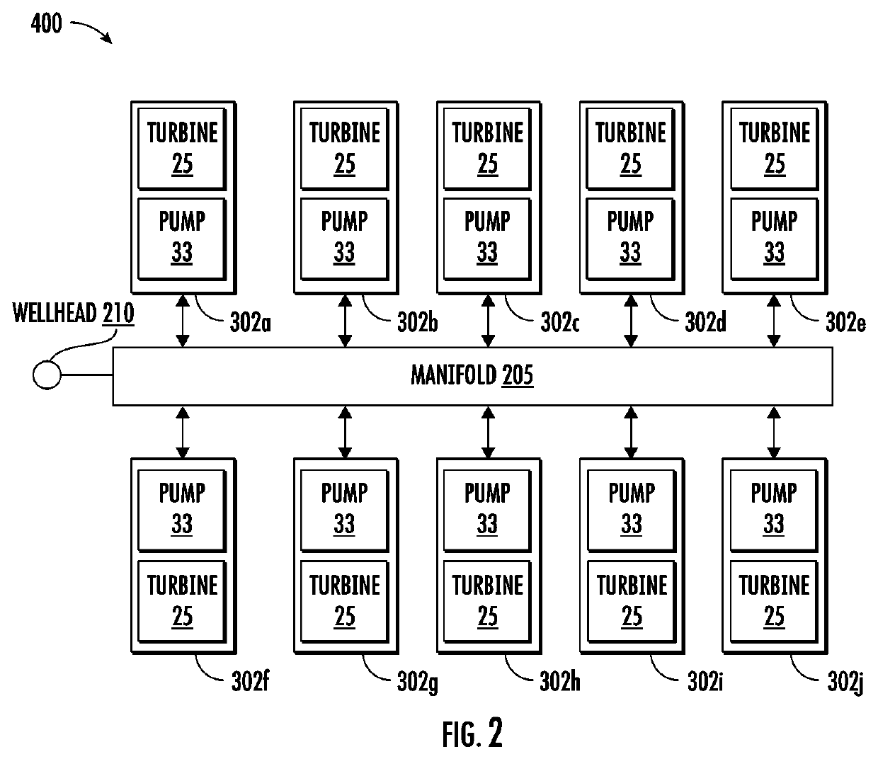
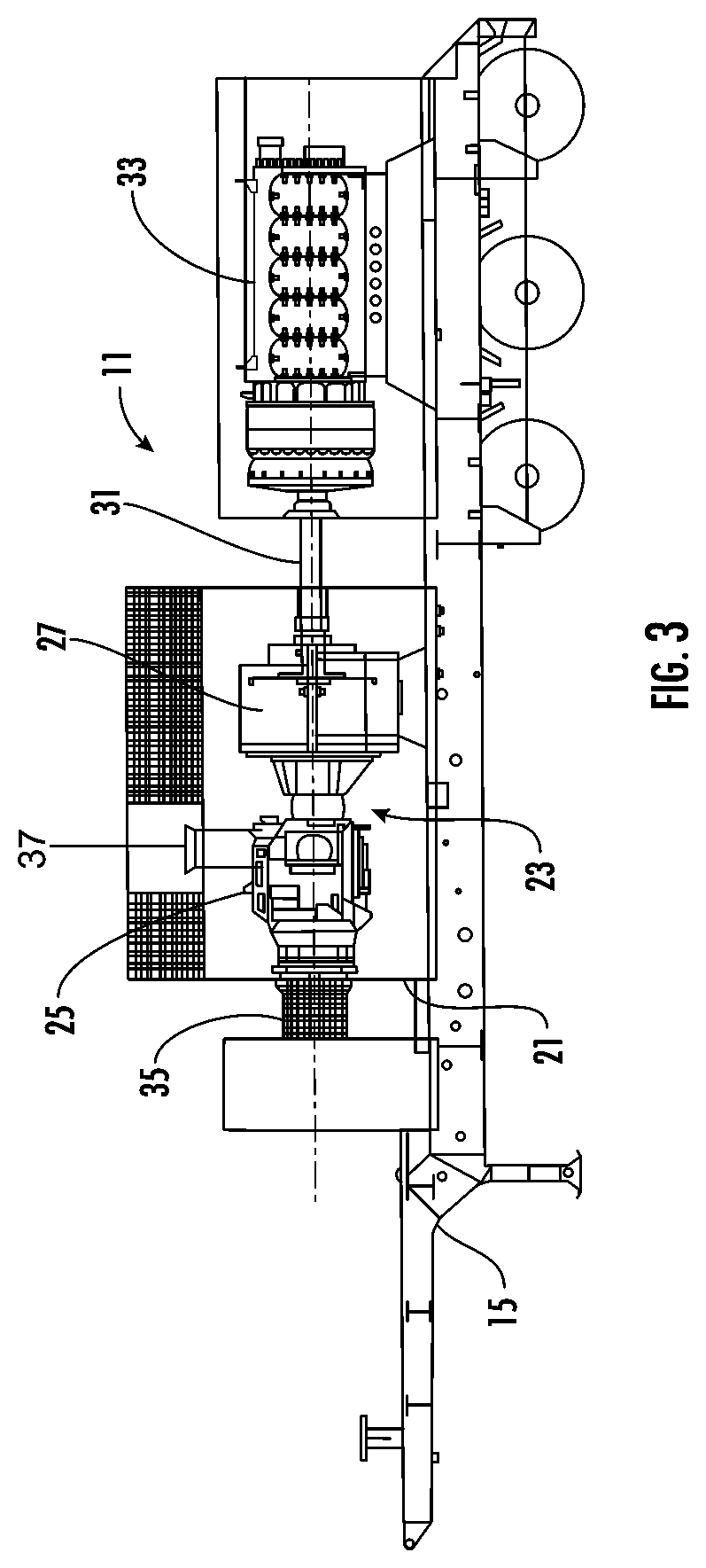
[0018]Generally, this disclosure is directed to methods and systems for controlling a fleet of DDT pumping units 11 (FIG. 3) as part of a high-pressure, high-power, fluid pumping system 400 (FIG. 2) for use in hydraulic fracturing operations. The systems and method of the present disclosure, for example, help reduce or eliminate the need for a spare pumping unit to be associated with the fluid pumping system 400, among other features.

[0019]FIG. 3 illustrates a schematic view of a pumping unit 11 for use in a high-pressure, high power, fluid pumping system 400 (FIG. 2) for use in hydraulic fracturing operations according to one embodiment of the disclosure. FIG. 2 shows a pad layout of the pumping units 11 (indicated as 302a thru 302j) with the pumping units all operatively connected to a manifold 205 that is operatively connected to a wellhead 210. By way of an example, the system 400 is a hydraulic fracturing application that may be sized to deliver a total Hydraulic Horse Power (H...


PUM


Abstract

A system and method for operating a fleet of pumps for a turbine driven fracturing pump system used in hydraulic fracturing is disclosed. In an embodiment, a method of operating a fleet of pumps associated with a hydraulic fracturing system includes receiving a demand Hydraulic Horse Power (HHP) signal. The demand HHP signal may include the Horse Power (HP) required for the hydraulic fracturing system to operate and may include consideration for frictional and other losses. The method further includes operating all available pump units at a percentage of rating below Maximum Continuous Power (MCP) level, based at least in part on the demand HHP signal. Furthermore, the method may include receiving a signal for loss of power from one or more pump units. The method further includes operating one or more units at MCP level and operating one or more units at Maximum Intermittent Power (MIP) level to meet the demand HHP signal.

Description

CROSS REFERENCE TO RELATED APPLICATIONS[0001]This application claims the benefit of and priority to U.S. Provisional Patent Application No. 62 / 899,951, which was filed on Sep. 13, 2019, and hereby is incorporated by reference for all purposes as if presented herein in its entirety.BACKGROUND OF THE DISCLOSURE[0002]This disclosure relates to operating a fleet of pumps for hydraulic fracturing and, in particular, to systems and methods for operating a directly driven turbine fracturing pump system for hydraulic fracturing application.[0003]Traditional Diesel fracturing pumping fleets have a large footprint and often need additional auxiliary equipment to achieve the horsepower required for hydraulic fracturing. FIG. 1 shows a typical pad layout for a fracturing pump system 100 including fracturing or frac pumps 101a through 101i, with the pumps all being driven by a diesel powered engine and operatively connected to a manifold 105 that is operatively connected to a wellhead 110. By wa...

Claims


Application Information

Patent Timeline
IPC IPC(8): E21B43/26F04B49/20F04B23/04
CPCF04B49/20E21B43/2607F04B23/04F04B2201/1203F04B23/06F04B9/02F04B49/007F04B51/00F04B49/065F04B49/02F04B49/10F04B2203/11F04B17/05E21B43/26
Inventor YEUNG, TONYRODRIGUEZ-RAMON, RICARDOFU, DIANKUIZEMLAK, WARRENSETH, SAMIR NATHFOSTER, JOSEPH
Owner BJ ENERGY SOLUTIONS LLC FORMERLY TES ASSET ACQUISITION LLC
Why Eureka
Try Eureka