Calibration techniques in haptic systems

a technology of haptic systems and calibration techniques, applied in the field of improved calibration techniques of hapticbased systems, can solve the problems of time-consuming, prone to human error, and inability to achieve ideal configurations,

Active Publication Date: 2020-10-27
ULTRAHAPTICS IP LTD
View PDF129 Cites 20 Cited by
  • Summary
  • Abstract
  • Description
  • Claims
  • Application Information

AI Technical Summary

Problems solved by technology

However, because complete control of space is not possible, controlling the acoustic field at given points yields erroneous local maxima in the acoustic field levels at other related positions.
In relation to mid-air haptic feedback, these can interfere in interactions with the space by creating secondary effects and ghost phenomena that can be felt outside the interaction area.
In reality, however, due to physical manufacturing and production constraints inherent in the process of electronic design and layout these ideal configurations are often not achievable.
Although this process could be performed manually this would be time consuming and prone to human error and as such an automated approach would be preferable.
However, this requires human interaction and so is subject to human error, as well as requiring human intervention in a more general sense.
Because complete control of space is not possible, controlling the acoustic field at given points may yield erroneous local maxima in the acoustic field levels at other related positions.
In relation to mid-air haptic feedback, these can interfere in interactions with the space by creating secondary effects and ghost phenomena that can be felt outside the interaction area.
Nevertheless, the packing of the transducer elements 510 is heavily compromised.
This yields lower intensities at the control point foci as well as unpredictable variations in local transducer density.
A random or Poisson disk sampling may be effective to eliminate these effects, but this has a downside of reducing the ability to pack the elements.
However, these sparse transducers at the edge remain able to suppress excess noise, at the cost of a larger footprint and some extra transducers.
This low shape quality can be attributed to a shallow angle of the control points that make up the shape.
Counter-intuitively, rotating each transducer further to point directly at the center of the shape actually degrades focusing performance, as the lack of resolving power perpendicular to the four sides of the array creates more powerful secondary maxima in the plane of the shape.
The first and most obvious side effect is that a high level of noise may interfere with the mid-air haptic qualities of the array.
They may cause phantom points and low level stimulation that can drown out the intended signal.
Another side effect is that since the array produces sound as a side effect, stronger random secondary maxima may result in more audible noise outside the working volume.
If the physical limitation of the placing of each electronic component is applied to the ideal layout by pruning transducers that are inappropriately placed, the design becomes sparse and inefficient.
While this could be used as a starting point for further manual intervention in the placement of the transducer elements, this would be time consuming and would risk inadvertently compromising the optimal layout intended.
The challenge is that the fulfillment of positive constraints is required in the face of a desired placement of components which violates negative constraints.
At a predefined point, the spring may be configured to break, resulting in the deletion and possible relocation of the component.
As the simulation moves forwards in time, springs will constrict, which may pull components into better positions, while other constraints may push components away from their various preferred locations.
Abruptly applying constraints to the component layout may create uncertainty due to physical constraints being immediately and sharply violated.

Method used


Image

  • Calibration techniques in haptic systems
  • Calibration techniques in haptic systems
  • Calibration techniques in haptic systems

Examples


Embodiment Construction

[0037]Described herein are certain techniques to enhance calibration techniques in haptic systems. Some or all of these techniques may be used at the same time or one after the other in order to improve such calibration.

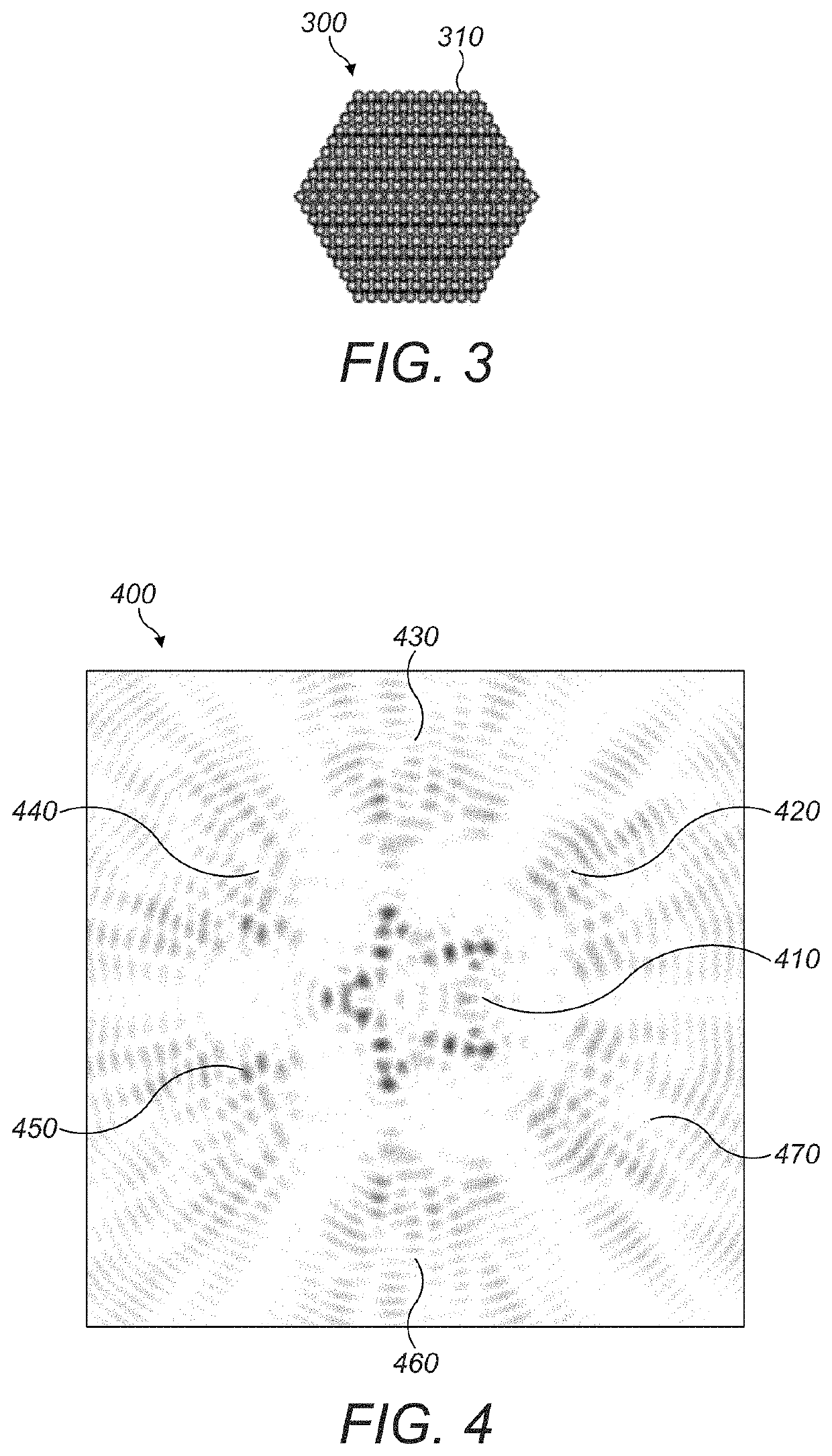
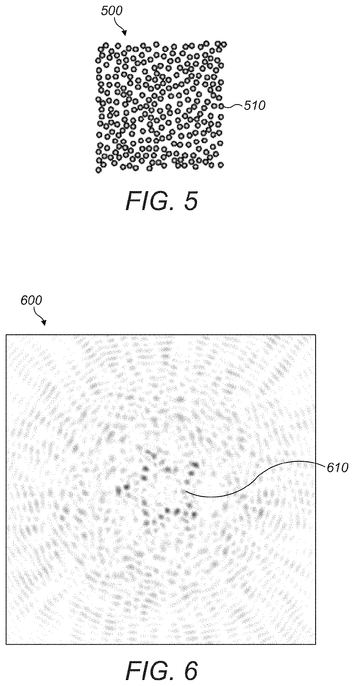
I. ARRAY CONFIGURATIONS TO REDUCE SECONDARY MAXIMA

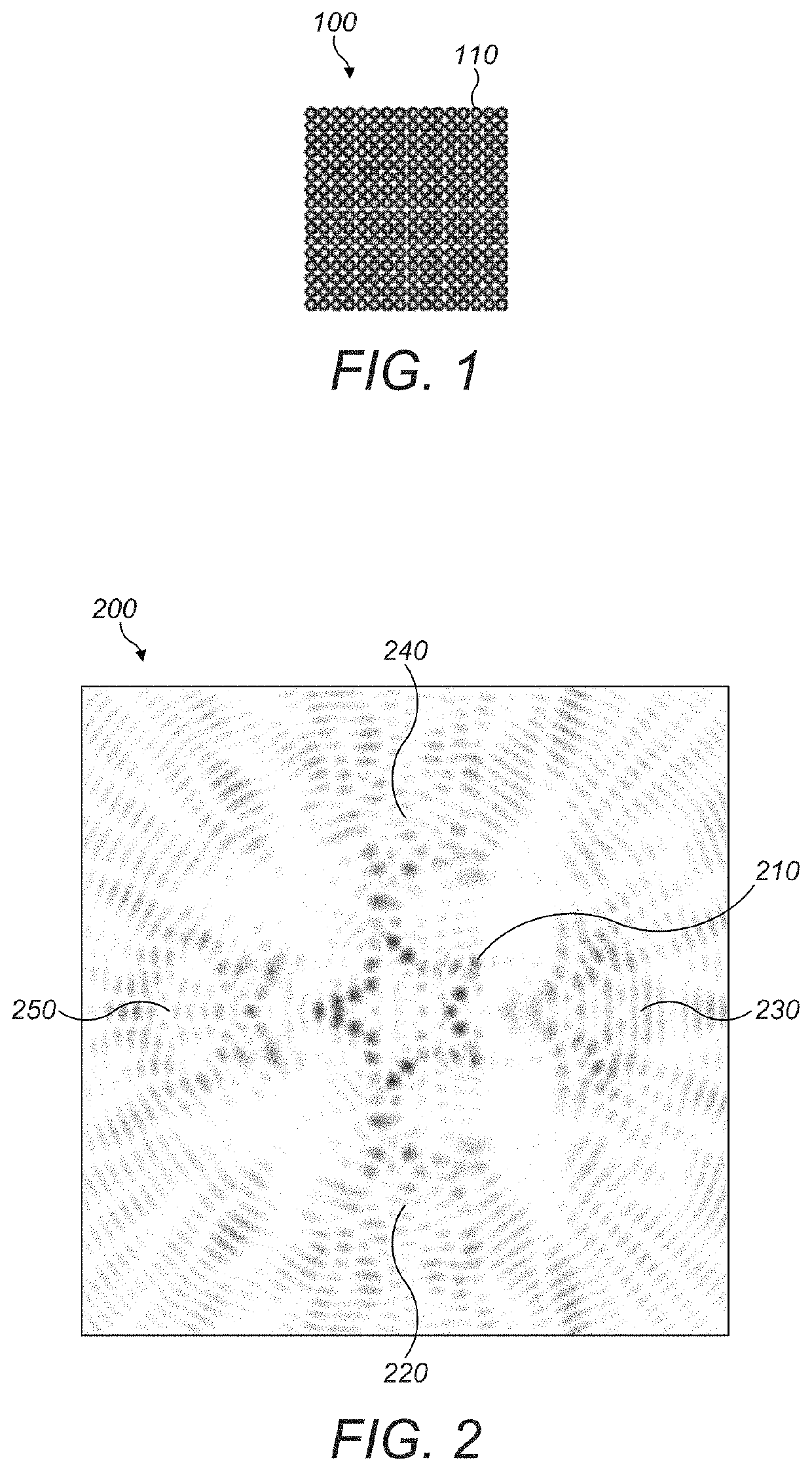
[0038]An acoustic field may be controlled by defining one or more control points in space. Each control point can be assigned a value equating to a desired amplitude at that control point. A physical set of transducers may then be controlled to create an acoustic field exhibiting the desired amplitude at the control points.

[0039]Because complete control of space is not possible, controlling the acoustic field at given points may yield erroneous local maxima in the acoustic field levels at other related positions. In relation to mid-air haptic feedback, these can interfere in interactions with the space by creating secondary effects and ghost phenomena that can be felt outside the interaction area.

[0040]The level and n...


PUM


Abstract

A system providing various improved calibration techniques for haptic feedback is described. An acoustic field is defined by one or more control points in a space within which the acoustic field may exist. Each control point is assigned an amplitude value equating to a desired amplitude of the acoustic field at the control point. Because complete control of space is not possible, controlling the acoustic field at given points yields erroneous local maxima in the acoustic field levels at other related positions. In relation to mid-air haptic feedback, these can interfere in interactions with the space by creating secondary effects and ghost phenomena that can be felt outside the interaction area. The level and nature of the secondary maxima in the acoustic field is determined by how the space is controlled. By arranging the transducer elements in different ways, unwanted effects on the acoustic field can be limited and controlled.

Description

RELATED APPLICATION[0001]This application claims the benefit of the following three U.S. Provisional Patent Applications, all of which are incorporated by reference in their entirety:[0002]1. Ser. No. 62 / 193,180, filed on Jul. 16, 2015.[0003]2. Ser. No. 62 / 275,206, filed on Jan. 5, 2016.[0004]3. Ser. No. 62 / 275,030, filed on Jan. 5, 2016.FIELD OF THE DISCLOSURE[0005]The present disclosure relates generally to improved calibration techniques for haptic-based systems.BACKGROUND[0006]A continuous distribution of sound energy, referred to as an “acoustic field”, may be used for a range of applications including haptic feedback in mid-air.[0007]By defining one or more control points in space, the acoustic field can be controlled. Each point can be assigned a value equating to a desired amplitude at the control point. A physical two-dimensional array of transducers can then be controlled to create an acoustic field exhibiting the desired amplitude at the control points.[0008]However, beca...

Claims


Application Information

Patent Timeline
Patent Type & Authority Patents(United States)
IPC IPC(8): H04B3/36G10K11/32G06F3/01G08B29/20G10K11/34G08B6/00G06F3/043
CPCG06F3/043G08B29/20G06F3/016G10K11/34G10K11/32G08B6/00
Inventor CARTER, THOMAS ANDREWLONG, BENJAMIN JOHN OLIVERBLENKINSOPP, ROBERT CHARLES
Owner ULTRAHAPTICS IP LTD
Why Eureka
Try Eureka