Volume sensor for combine harvester tailings return system

Active Publication Date: 2020-11-03
AGCO INT GMBH
View PDF11 Cites 0 Cited by
  • Summary
  • Abstract
  • Description
  • Claims
  • Application Information

AI Technical Summary

Benefits of technology

[0007]The ejection channel is typically devoid of any moving mechanical components and so the signal produced by the proximity sensor is ‘cleaner’ and a more reliable representation of the tailings volume.
[0013]In an alternative arrangement, the tailings may be delivered upstream of the (primary) threshing apparatus so as to avoid the need for a secondary threshing unit and to use the threshing apparatus to re-thresh the tailings.

Problems solved by technology

However, it has been found that such a sensing arrangement is suitable only for paddle elevators where the material is static upon the paddle.

Method used


Image

  • Volume sensor for combine harvester tailings return system
  • Volume sensor for combine harvester tailings return system
  • Volume sensor for combine harvester tailings return system

Examples


Embodiment Construction

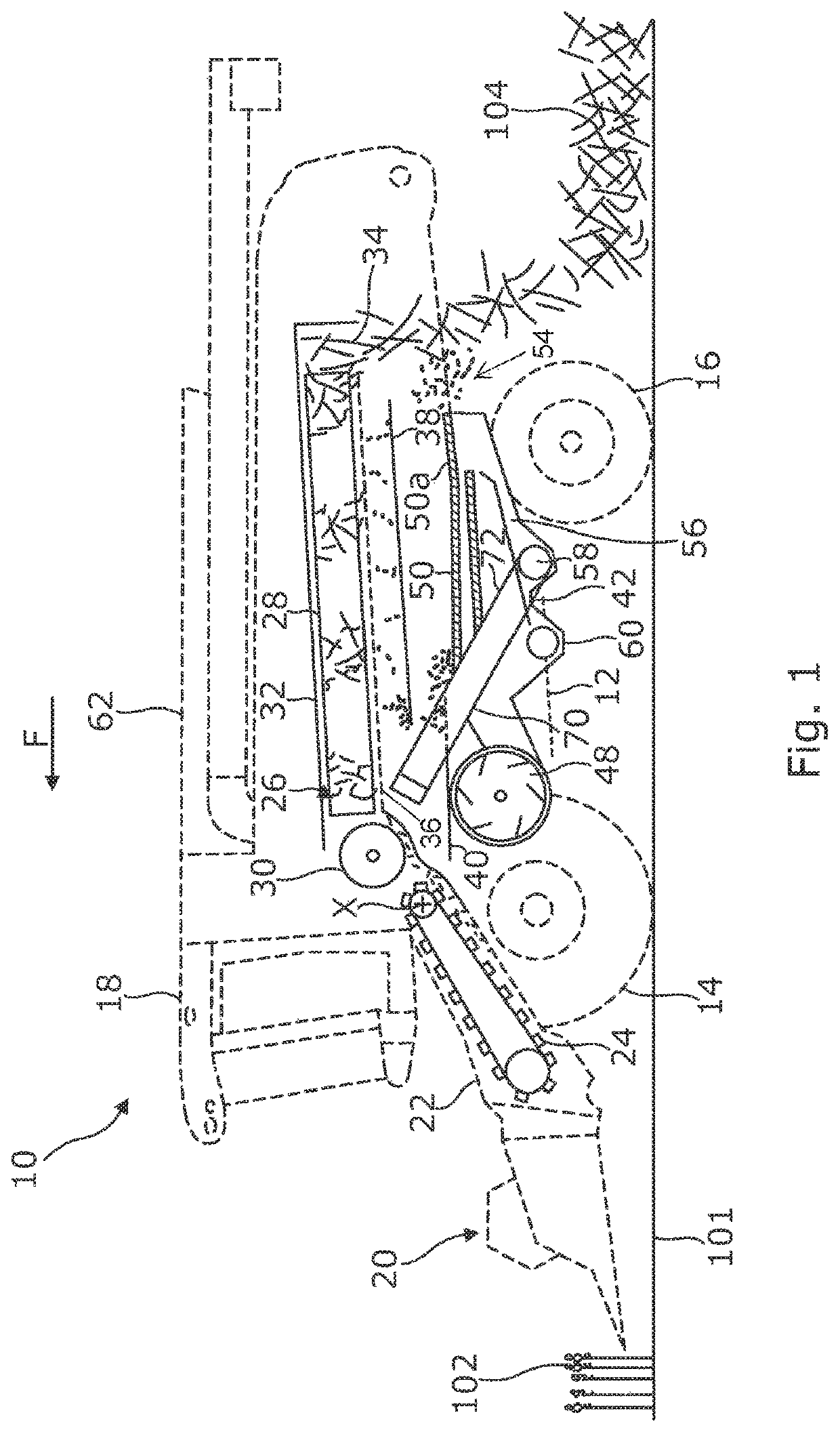
[0019]Relative terms such as forward, rearward, transverse, lateral, longitudinal, and sideways are in reference to the normal forward direction of travel of the combine 10 and indicated by arrow F. The terms vertical and horizontal are in reference to the level ground 101 upon which the combine 10 is disposed. In other words, the Cartesian axes of ‘longitudinal’, ‘transverse’, and ‘vertical’ are made in relation to the frame 12 of combine 10 and are not affected by any slope in the ground. The terms “upstream” and “downstream” are in reference of the general direction of crop flow along the material conveyance systems described.

[0020]FIG. 1 illustrates in schematic form the main components of a crop processing system of a combine harvester 10 and will be used to explain the flow of material below. The crop processing system is shown in solid lines, and the outline profile of harvester 10 is shown in dotted lines.

[0021]Combine harvester 10, hereinafter referred to as ‘combine,’ incl...


PUM


Abstract

A combine harvester tailings return system includes a tailings conveyor and an ejection channel for depositing tailings upstream of a cleaning system. A proximity sensor is mounted to the ejection channel and is configured to sense the height of a layer of tailings during transit through the returns system.

Description

FIELD[0001]This disclosure relates to combine harvesters and particularly to tailings return systems used therein, wherein the tailings return system serves to collect tailings screened out from a crop material stream by a grain cleaning system, and return the tailings to a location in the combine harvester upstream of the grain cleaning system for reprocessing.BACKGROUND[0002]The use of combine harvesters, hereinafter referred to as “combines,” in the agriculture industry is well established, and so too are the principles upon which they operate. In general, combines carry a header for cutting and / or gathering a crop as the machine is driven across a crop field. The crop stream passes through threshing apparatus and separating apparatus. Residue straw is ejected from the rear of the machine either in a deposited windrow for subsequent baling, or chopped and spread. The portion of crop material, typically made up of grain and material other than grain (MOG) such as chaff and unthres...

Claims


Application Information

Patent Timeline
Patent Type & Authority Patents(United States)
IPC IPC(8): A01D41/127A01F12/52A01F12/46A01F12/18B65G33/26
CPCA01F12/52A01D41/127B65G33/265B60Y2200/222A01F12/46A01F2012/188A01F12/18A01D41/1271
Inventor HERMANN, DANBILDE, MORTEN LETH
Owner AGCO INT GMBH
Why Eureka
Try Eureka