
Foam reefer wall using “loop” scrim fabric backing

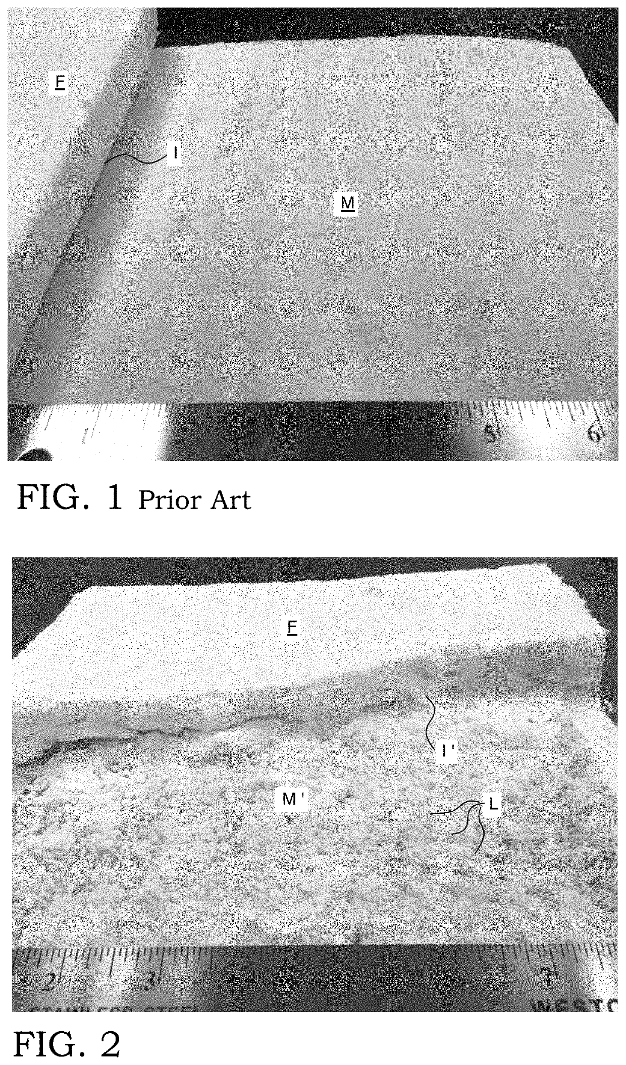
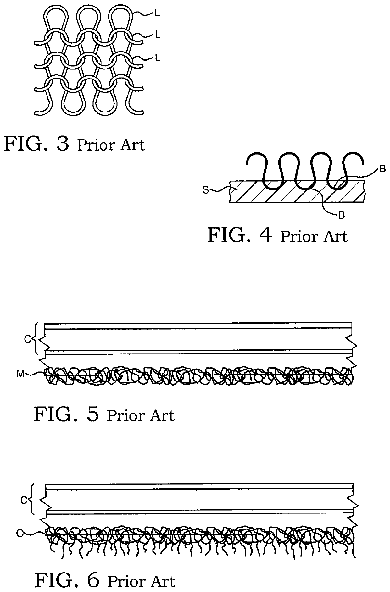
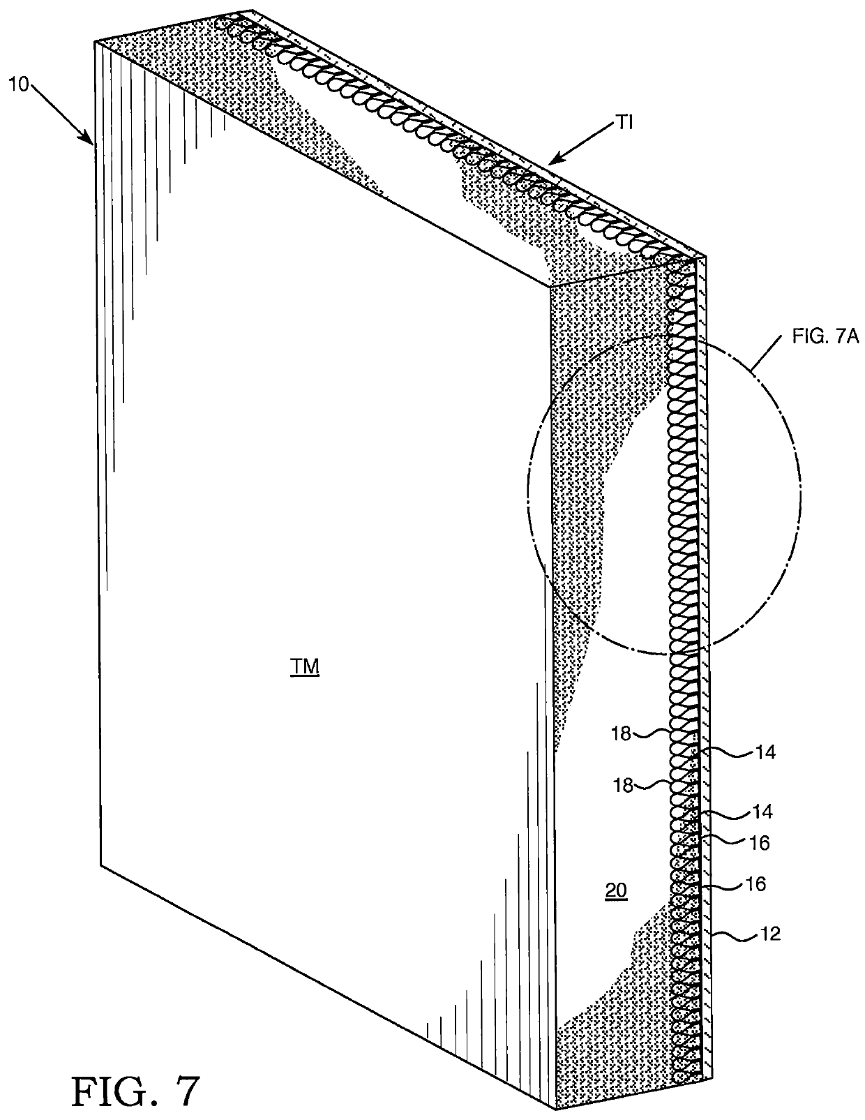
a technology of scrim fabric and foam reefer, which is applied in the direction of transportation and packaging, rigid containers, other domestic articles, etc., can solve the problems of inherently increasing the bonding capability of the panel, reducing the adhesion, and reducing the bonding strength of the panel, so as to reduce the potential downtime, reduce the effect of thermal efficiency loss and greater adhesion

Active Publication Date: 2020-11-03
LAROCCO MICHAEL C
View PDF1 Cites 0 Cited by
  • Summary
  • Abstract
  • Description
  • Claims
  • Application Information

AI Technical Summary

Benefits of technology

The looped fabric backing system achieves a several-fold increase in foam adhesion, reducing potential downtime and repair costs, and extending the useful life of refrigerated units by providing greater resistance to damage and moisture, resulting in improved thermal efficiency and durability.

Problems solved by technology

Although the idea was novel and relevant at the time, it was later found to be too broad, encompassing “any” panel rather than just panels used for the interiors of refrigerated trailers, truck bodies, container, and rail cars, etc.
Various methods to enhance this bond have tried over the years with limited success.
They do not inherently increase the bonding capability of the panel and are thus no improvement to the standard scrim used since 1998.
Fork trucks and other freight loading mechanisms create tremendous pressure and damage to the inside of a refrigerated unit resulting pressure against the wall as cargo is loaded.
In most cases, the pressure causes the connection of point bond scrim to the insulating foam to delaminate due to crushing of the foam just beneath the reinforced panel.
The result of that delamination from the foam causes costly downtime with the need to remove walls and reattach elements with adhesives.
While methods to try to improve such bonding by scraping or lofting scrim, using intermediates including films, and other methods of foam bonding may have helped, they still have not eliminated the problem.
When a wall delaminates from the foam, it allows moisture to infiltrate resulting in loss of insulating efficiency properties.
That, in turn, leads to unit damage and the need for costly interior wall repair or replacement.

Method used


Image

  • Foam reefer wall using “loop” scrim fabric backing
  • Foam reefer wall using “loop” scrim fabric backing
  • Foam reefer wall using “loop” scrim fabric backing

Examples


Embodiment Construction

[0033]When referring to alternate embodiments, like that shown in FIG. 7B, common elements are commonly numbered though in the next hundred series.

[0034]When referring to any numerical length, width, percent improvement or other quantitative comparison number (or number range) herein, it should be noted that all such numbers are representative of embodiments of the invention as shown. Furthermore, any such range of numbers should expressly include each and every fraction or decimal between its stated minimum and maximum. For instance, any one component (of loop material) having from about 40 to 70 loops per square inch, should also specifically cover fabric backing substrates having about 41, 42 and 45 loops / in2 . . . and so on, up to about 65, 67 and 69.6 loops / in2. And for loop heights between abut 0.5 to 6 mm or more, preferably about 3 to 5 mm each, those loops would include all values between the aforementioned minimum and maximum loop heights. It is to be understood, however, ...


PUM

PropertyMeasurementUnit
heightsaaaaaaaaaa
heightsaaaaaaaaaa
heightaaaaaaaaaa

Abstract

An improved fabric backing for the manufacture of glass-reinforced thermoplastic panels that exhibits significantly greater foam adhesion than its scrim counterpart. That fabric backing includes a plurality of looped section extending upwardly (and inwardly) from its base for enhancing adhesion thereto. The combination is subjected to lamination for making an improved glass-reinforced thermoplastic interior wall panel. That wall panel can be used in a storage unit, such as a refrigerated trailer, railcar, shipping container and / or box truck.

Description

CROSS-REFERENCE TO RELATED APPLICATION[0001]This is a perfection of provisional application Ser. No. 62 / 316,751, filed on Apr. 1, 2016, the disclosure of which is fully incorporated by reference herein.BACKGROUND OF THE INVENTION[0002]Since 1998, Applicant has used a polyester point bond fabric backing, or “scrim”, on his glass-reinforced thermoplastic panels (GRTP) for the interior walls of refrigerated trailers, railcars, shipping containers, box trucks, and general refrigeration storage / transportation units. The idea for using scrim was originally developed to allow for good bonding during the foaming process whereby insulating foam gets poured, in liquid form, between the cavity of the inner wall (GRTP) and outer wall (metal skin). As that foam catalyzes and solidifies, it soaks into and bonds to the polyester point bond scrim backing thereby allowing the material to stick to the GRTP. Without the scrim, the foam would not bond at all.[0003]The Applicant was granted U.S. Pat. No...

Claims


Application Information

Patent Timeline
Patent Type & Authority Patents(United States)
IPC IPC(8): B32B5/02B65D90/02B32B5/24B32B5/20B32B7/08B32B1/02B32B7/12B32B1/08B32B3/08B32B15/04B32B1/00
CPCB32B3/08B32B5/02B32B7/08B32B5/20B32B1/02B32B5/022B65D90/022B32B5/245B32B5/024B32B7/12B32B5/028B32B1/08B32B15/046B32B2607/00B32B2266/0257B32B2262/0253B32B2307/304B32B2262/0261B32B2605/00B32B2250/05B32B2266/025B32B2260/021B32B2262/101B32B2266/0228B32B2605/08B32B2262/0276B32B2260/046B32B2266/0235B32B2266/0264B32B2605/10B32B2439/62B32B2307/50B32B5/06B32B1/00
Inventor LAROCCO, MICHAEL C.
Owner LAROCCO MICHAEL C
Learn More