Method and apparatus for multi-part close fitting head coil

Active Publication Date: 2020-11-10
LIFE SERVICES
View PDF113 Cites 7 Cited by
  • Summary
  • Abstract
  • Description
  • Claims
  • Application Information

AI Technical Summary

Benefits of technology

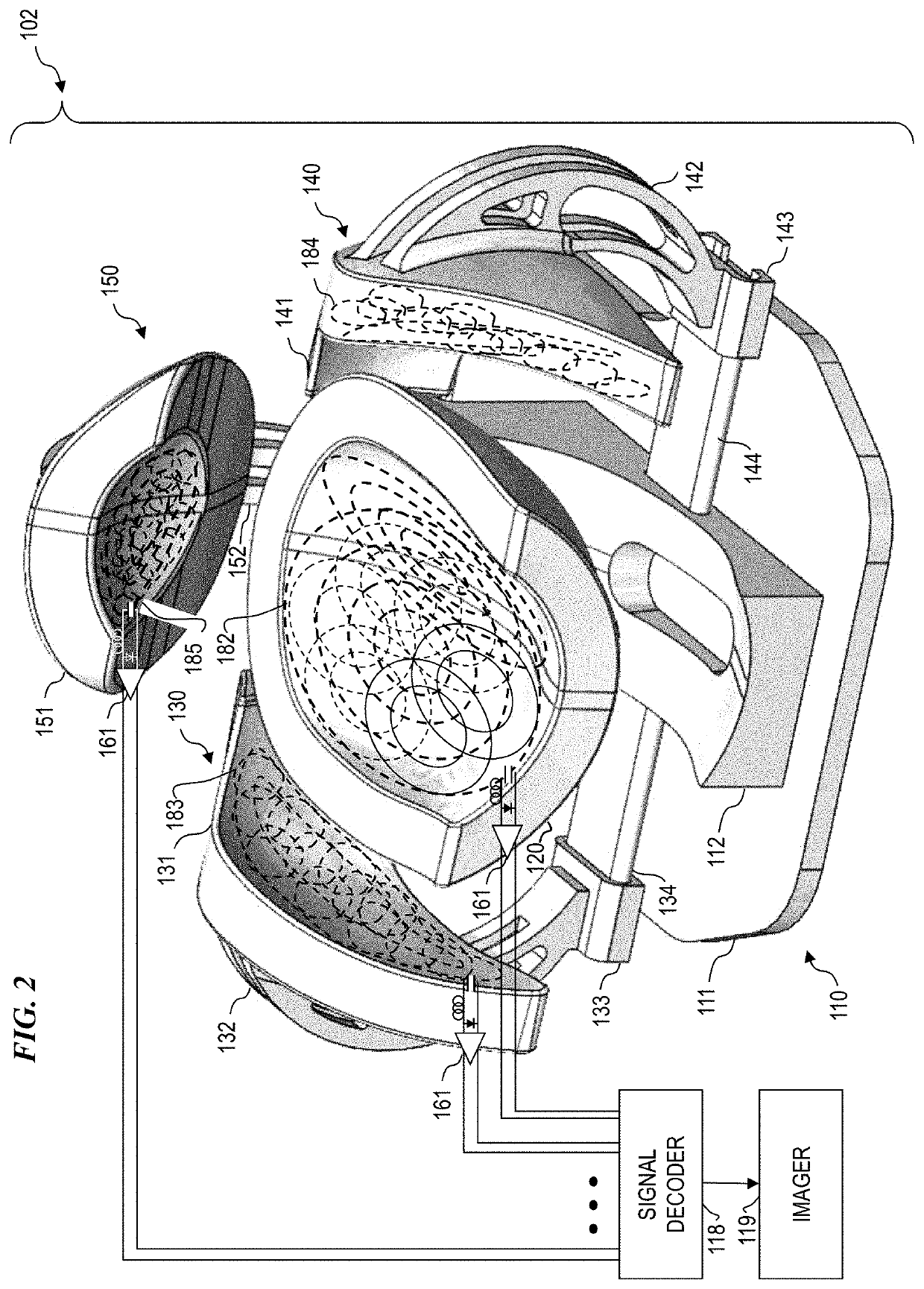
[0049]In contrast to U.S. Pat. No. 6,534,983 to Boskamp et al. (where the geometric shape of each of the coil loops and the overlap area are configured to cause a mutual inductance between every pair of the coil loops to be less than 10 percent of the self-inductance of each of the N coils), some embodiments of the present invention use concentric and/or overlapped coil loops, each coil loop having one or more individual preamplifiers. In some embodiments, the plurality of loops of the present invention will be arranged to reduce mutual inductance, but the greater number of coil loops is used to advantage in order to achieve g

Problems solved by technology

Low-power circuits can use varactors (electrically variable capacitors), field-effect transistors (used as variable gain elements or variable resistors) and like components that are directly electrically-adjustable, for use in adjusting frequency, impedance or other circuit characteristics and parameters, however such components are often unsuitable or inoperat

Method used


Image

  • Method and apparatus for multi-part close fitting head coil
  • Method and apparatus for multi-part close fitting head coil
  • Method and apparatus for multi-part close fitting head coil

Examples


Embodiment Construction

[0078]Although the following detailed description contains many specifics for the purpose of illustration, a person of ordinary skill in the art will appreciate that many variations and alterations to the following details are within the scope of the invention. Specific examples are used to illustrate particular embodiments; however, the invention described in the claims is not intended to be limited to only these examples, but rather includes the full scope of the attached claims. Accordingly, the following preferred embodiments of the invention are set forth without any loss of generality to, and without imposing limitations upon the claimed invention. Further, in the following detailed description of the preferred embodiments, reference is made to the accompanying drawings that form a part hereof, and in which are shown by way of illustration specific embodiments in which the invention may be practiced. It is understood that other embodiments may be utilized and structural change...


PUM


Abstract

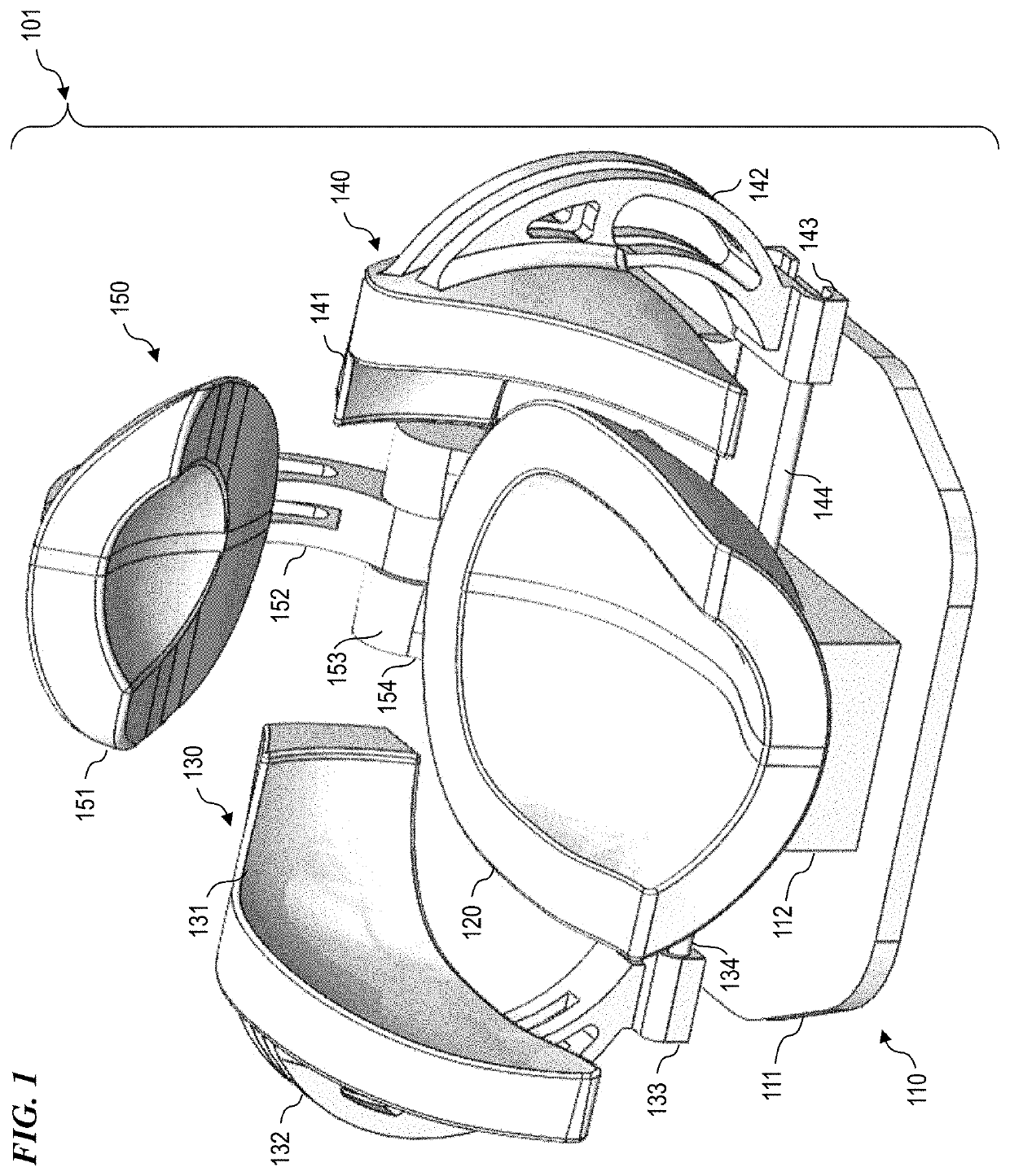
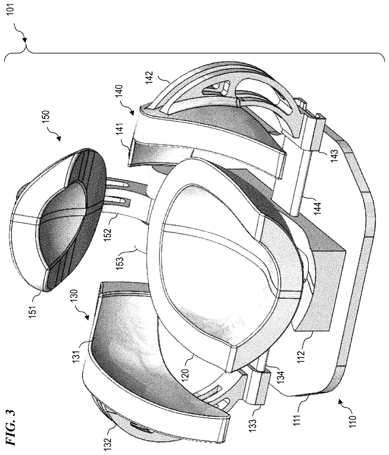
A method and apparatus for receiving (RX) radio-frequency (RF) signals suitable for MRI and/or MRS from a plurality of MRI “coil loops” in each of a plurality of coil parts, each coil part having a subset of the total number of coil loops. In some embodiments, a first base part, optionally having no coils, is used to provide support of the plurality of coil parts, wherein the plurality of coil parts include a second part holding back-of-the-head coil loops, a third part holding right-side-of-the-head coil loops, a fourth part holding right-side-of-the-head coil loops, and a fifth part holding top-of-the-head coil loops. In some embodiments, the system provides for repeatable positioning, frequency tuning, and impedance matching such that experimental conditions can be replicated for later examinations of each of a plurality of patients having differing impacts on positioning, tuning and matching of the various coil parts.

Description

CROSS-REFERENCE TO RELATED APPLICATIONS[0001]This application claims priority benefit, under 35 U.S.C. § 119(e), of U.S. Provisional Patent Application No. 62 / 260,236 filed Nov. 25, 2015 by Brandon J. Tramm et al., titled “Method and apparatus for multi-part close-fitting head coil,” which is incorporated herein by reference in its entirety.[0002]This application is related to:[0003]U.S. Provisional Patent Application No. 61 / 906,409 filed Nov. 19, 2013 by Brandon J. Tramm, titled “Method and apparatus for adjustable earpieces in an MRI system,”[0004]U.S. patent application Ser. No. 14 / 538,635 filed Nov. 11, 2014 by Brandon J. Tramm, titled “Method and apparatus for adjustable earpieces in an MRI system” (which issued as U.S. Pat. No. 9,700,232 on Jul. 11, 2017),[0005]U.S. patent application Ser. No. 14 / 548,276 filed Nov. 19, 2014 by Brandon J. Tramm et al., titled “Method and positionable patient-interface apparatus for an MRI system” (which issued as U.S. Pat. No. 9,820,676 on Nov....

Claims


Application Information

Patent Timeline
IPC IPC(8): A61B5/055A61B5/00G01R33/36G01R33/341G01R33/34
CPCG01R33/34A61B5/0042G01R33/341A61B5/0555G01R33/3614A61B5/7405A61B5/055G01R33/34007G01R33/34084G01R33/3415G01R33/3628
Inventor TRAMM, BRANDON J.LEMAIRE, CHARLES A.WAKS, MATTHEW T.SCHILLAK, SCOTT M.
Owner LIFE SERVICES
Why Eureka
Try Eureka