Voltage regulator

a voltage regulator and voltage regulator technology, applied in the direction of pulse technique, process and machine control, instruments, etc., can solve the problems of complex layout and increase in chip area, and achieve the effect of little layout constrain

Active Publication Date: 2020-11-10
ABLIC INC
View PDF11 Cites 1 Cited by
  • Summary
  • Abstract
  • Description
  • Claims
  • Application Information

AI Technical Summary

Benefits of technology

[0012]The present invention provides a voltage regulator having an overcurrent protection circuit which receives little constraint in layout and copes with malfunctions due to a parasitic bipolar transistor at the time of ground fault of an output terminal.
[0014]Since a voltage regulator of the present invention includes a protection circuit which prevents an overcurrent when an output terminal becomes a negative voltage upon ground fault of a load, an overcurrent protection circuit can be constructed under little constraint in layout.

Problems solved by technology

Since measures on layout such as increasing the distance between transistors, etc., are taken to avoid the above state, a constraint in layout is imposed, thereby causing the complexity of the layout, an increase in chip area, etc.

Method used


Image

  • Voltage regulator
  • Voltage regulator
  • Voltage regulator

Examples


Embodiment Construction

[0020]Embodiments of the present invention will hereinafter be described with reference to the accompanying drawings.

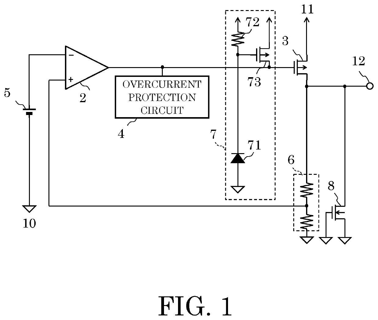
[0021]FIG. 1 is a circuit diagram illustrating a voltage regulator according to an embodiment of the present invention.

[0022]The voltage regulator according to the embodiment has an error amplifier circuit 2, a PMOS transistor 3 being an output transistor, an overcurrent protection circuit 4, a reference voltage circuit 5, a resistance circuit 6, a protection circuit 7, an NMOS transistor 8 being a clamp circuit, and an output terminal 12. The protection circuit 7 has a diode 71, a resistor 72, and a PMOS transistor 73. The NMOS transistor 8 is an ESD protection element. Although described later, the protection circuit 7 is constructed to include a drain region of the NMOS transistor 8.

[0023]A description will next be made of connections of the voltage regulator according to the embodiment.

[0024]The error amplifier circuit 2 has an inversion input terminal connected t...


PUM

PropertyMeasurementUnit
gate voltageaaaaaaaaaa
voltageaaaaaaaaaa
drain voltagesaaaaaaaaaa

Abstract

A voltage regulator includes an error amplifier circuit which controls a gate voltage of an output transistor, an overcurrent protection circuit which prevents an overcurrent of the output transistor, and a protection circuit which detects a negative voltage of an output terminal and controls a gate voltage of the output transistor to suppress an overcurrent. The protection circuit includes a MOS transistor which controls the gate voltage of the output transistor, a clamp circuit connected to a gate of the MOS transistor, a semiconductor element having an N-type region connected to the clamp circuit, and a parasitic bipolar transistor constructed from an N-type region connected to the output terminal as an emitter, a P-type substrate as a base, and the N-type region of the semiconductor element as a collector.

Description

RELATED APPLICATIONS[0001]This application claims priority under 35 U.S.C. § 119 to Japanese Patent Application No. 2018-060314 filed on Mar. 27, 2018, the entire content of which is hereby incorporated by reference.BACKGROUND OF THE INVENTION1. Field of the Invention[0002]The present invention relates to a voltage regulator.2. Description of the Related Art[0003]A voltage regulator generally includes an overcurrent protection circuit. Various inventions have been made to the protection circuit because accuracy is required for the protection circuit (refer to, for example, Japanese Patent Application Laid-Open No. 2003-29856).[0004]FIG. 4 is a circuit diagram illustrating a voltage regulator having an overcurrent protection circuit in related art.[0005]The voltage regulator in related art includes an error amplifier circuit 102 which receives a feedback voltage based on an output voltage of an output terminal 101 and a reference voltage, an output transistor 103, and an overcurrent ...

Claims


Application Information

Patent Timeline
Patent Type & Authority Patents(United States)
IPC IPC(8): G05F1/573H02H1/00H03K17/082H02H9/02
CPCH02H1/0007H02H9/02G05F1/573H02H9/025H03K17/0822G05F1/56G05F1/571
Inventor TOMIOKA, TSUTOMUKURODA, TADAKATSUSUGIURA, MASAKAZU
Owner ABLIC INC
Why Eureka
Try Eureka