Headrest folding device

a folding device and headrest technology, applied in the direction of gearing, vehicle components, vehicle arrangement, etc., can solve the problems of large space occupied by the device, complex headrest folding device of the prior art, and more number of components, so as to achieve compact device, fold stably, and reduce the effect of space occupation

Active Publication Date: 2020-11-17
WOOBO TECH CO LTD
View PDF27 Cites 4 Cited by
  • Summary
  • Abstract
  • Description
  • Claims
  • Application Information

AI Technical Summary

Benefits of technology

[0019]According to a headrest folding device as described above, there are advantageous effects as follows.
[0020]Its structure can be significantly simplified, the device becomes compact, and the headrest can be folded stably, by including: a housing; a pair of links rotatably installed in the housing; and a lifting member installed in the housing in a way that it can be lifted or lowered, wherein a stay rod is connected to the links, and wherein the stay rod is slidingly installed in the lifting member. Besides, the durability of the device is enhanced since the stay rod being connected to the headrest is dividedly supported by the links and the lifting member.
[0021]A screw rotatably installed in the housing and driven by a motor is further included, wherein the screw is screw-coupled to the lifting member, so that the lifting member can be lifted or lowered more stably.
[0022]The housing comprises sidewalls respectively disposed at both sides thereof and a mid-wall disposed between the both sidewalls, wherein the links are installed in the both sidewalls respectively, wherein the screw is rotatably installed in the mid-wall, wherein the lifting member is disposed between the both sidewalls, wherein the stay rod comprises a first bar disposed along the left-to-right direction and a second bar disposed formed at both sides of the first bar and disposed along the up-down direction, wherein the first bar is slidingly installed along the front-to-rear direction in the lifting member, wherein the first bar is disposed at the rear side of the screw, and wherein the both sides of the first bar can be respectively connected to the links, so that the device can be maintained compactly, and at the same time, the supporting force for the headrest can be evenly distributed among the both sides and the center of the stay rod, and thus, the durability of the device is more enhanced thereby.
[0023]A guide slot wherein the first bar is inserted is formed in the lifting member along the front-to-rear direction, and the guide slot is formed to have an open rear side so that it can be assembled by inserting the stay rod into the lifting member through the open portion, thereby possibly further facilitating the assembly.
[0024]A lift guide rod is installed in the housing, and a lift guide groove wherein the lift guide rod is inserted is formed in the lifting member, so that the housing can be formed by using a press, thereby possibly facilitating the manufacturing of the housing. Besides, the durability of the device is enhanced further.

Problems solved by technology

Thus, since the separation distance between the rotating member 50 and the mounting portion must be large in order to increase the folding angle of the headrest, there is a problem that the space occupied by the device becomes large.
Besides, the structure of such a headrest folding device of the prior art is complicated so that there is a problem that it requires more number of components.
Moreover, since it is supported only at both sides of the headrest, there is a problem that the durability is degraded.

Method used


Image

  • Headrest folding device
  • Headrest folding device
  • Headrest folding device

Examples


embodiment 1

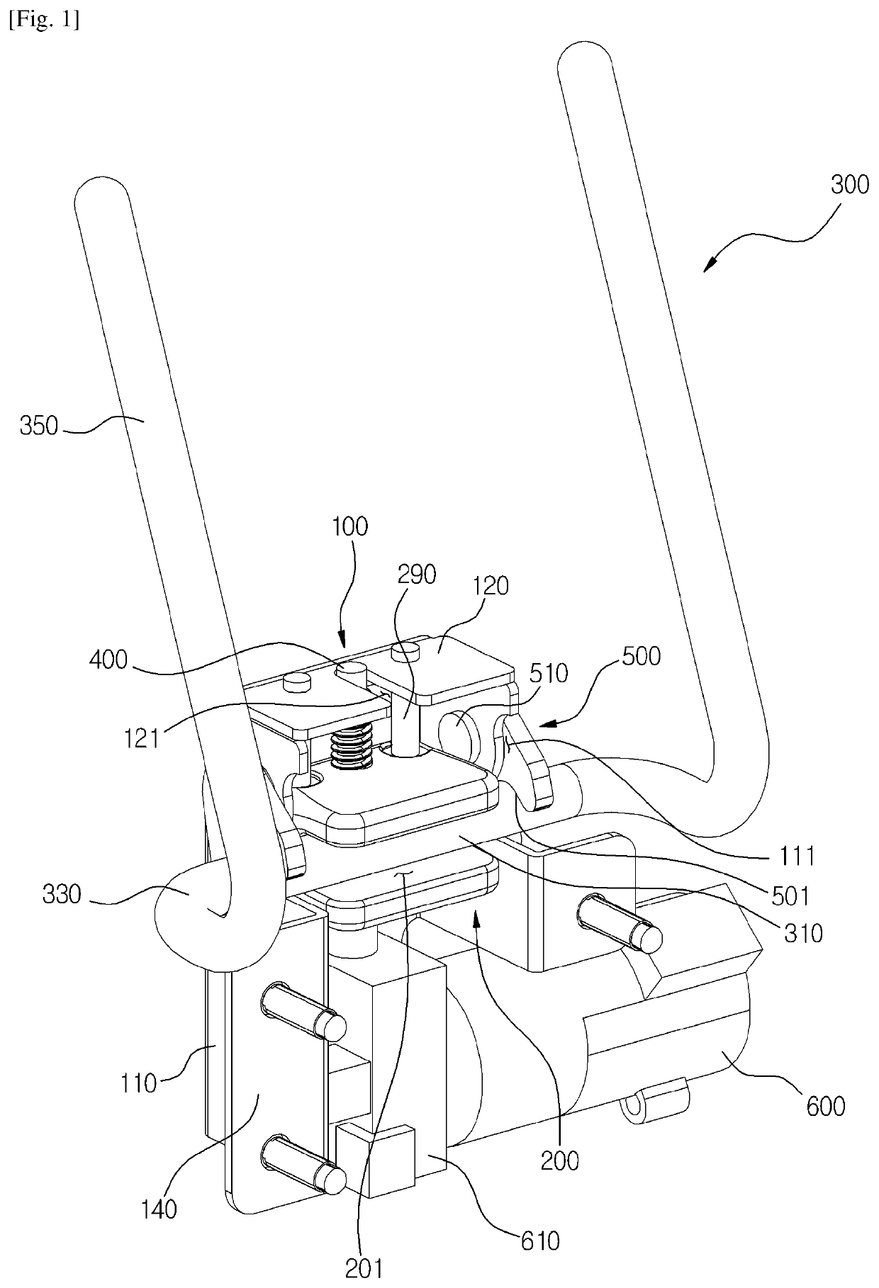
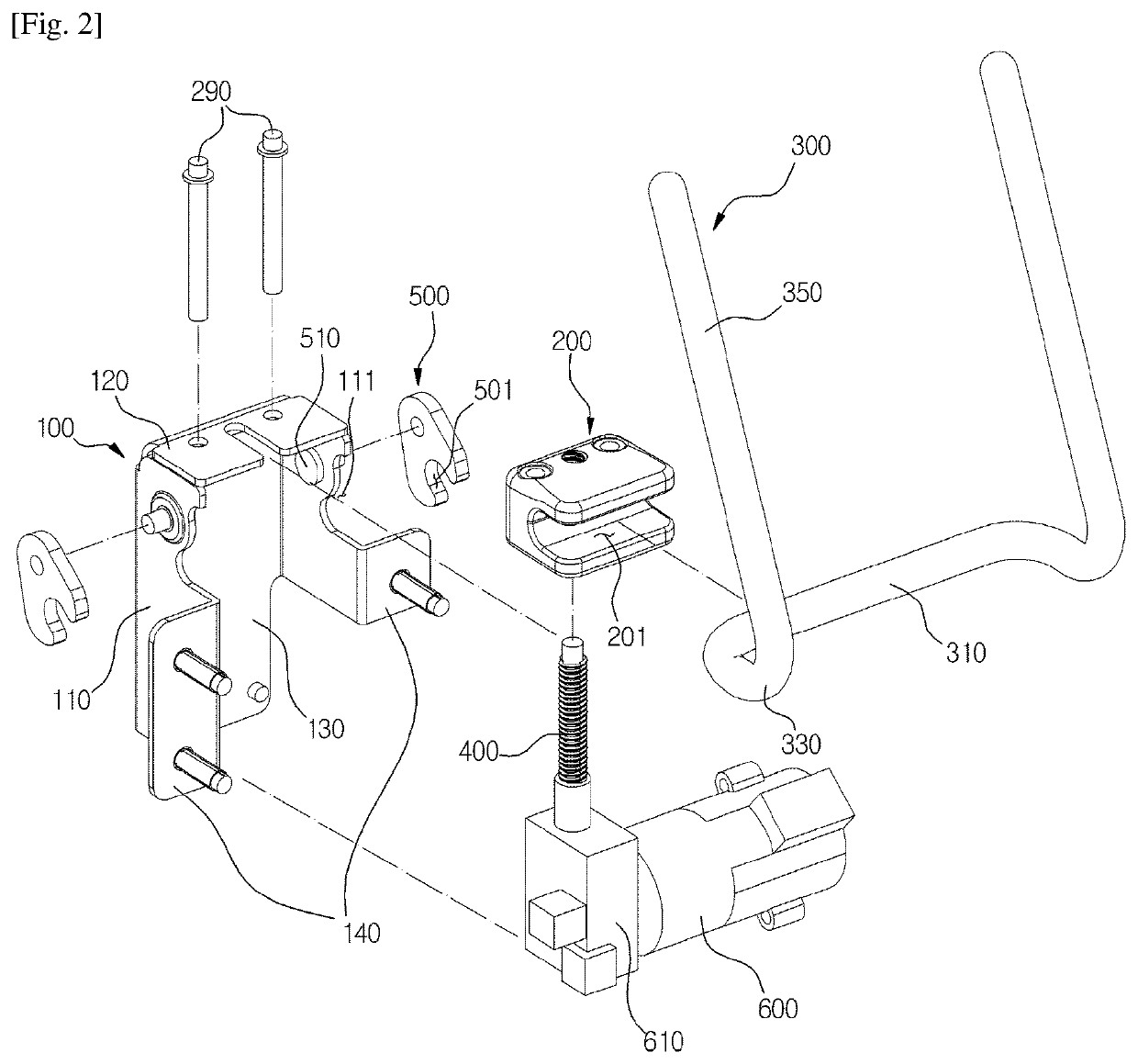
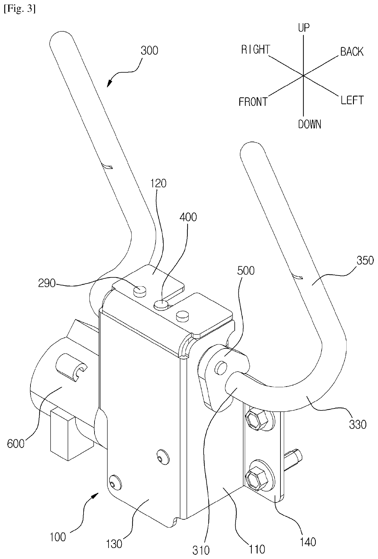
[0049]As illustrated in FIGS. 1 to 5, a headrest folding device of the first exemplary embodiment is characterized in that and comprises: a housing 100; a pair of links 500 rotatably installed in the housing 100; and a lifting member 200 installed in the housing 100 in a way that it can be lifted or lowered, wherein a stay rod 300 is connected to the links 500, and wherein the stay rod 300 is slidingly installed in the lifting member 200.

[0050]The housing 100 comprises: a front surface 130; sidewalls 110 respectively disposed at both sides of the front surface 130; and a mid-wall 120 disposed between the both sidewalls 110.

[0051]The housing 100 is integrally formed with the first surface 130, the side walls 110, and the mid-wall 120.

[0052]In this exemplary embodiment and the exemplary embodiments hereinafter, the front side means the folding direction of the headrest.

[0053]The front surface 130 is formed with a flat plate, and formed to be a rectangular whose up-down length is longe...

embodiment 2

[0129]In describing the headrest folding device according to the second exemplary embodiment of the present invention, same symbols will be used for the same or the similar elements as those of the headrest folding device according to the first exemplary embodiment of the present invention, and the detailed description and illustration will be omitted.

[0130]As illustrated in FIG. 6, the headrest folding device according to the second exemplary embodiment is characterized in that the driving force of a motor 1600 is delivered to a screw 1400 through a flexible shaft 1620.

[0131]The motor 1600 is not installed in a housing 1100, but instead, disposed apart from the housing 1100. The motor 1600 can be installed at the side of a seat. That is, the motor 1600 may freely installed in the other places not in the upper center of the seat wherein the housing 1100 is installed. Thus, the motor 1600 can be more effectively protected from the foreign substances or water. Also, since the motor 16...

embodiment 3

[0136]In describing the headrest folding device according to the third exemplary embodiment of the present invention, same symbols will be used for the same or the similar elements as those of the headrest folding device according to the first and the second exemplary embodiments of the present invention, and the detailed description and illustration will be omitted.

[0137]As illustrated in FIGS. 7 to 9, it is characterized in that a housing 2100 of the headrest folding device according to the third exemplary embodiment is installed in the headrest.

[0138]The housing 2100 of the present exemplary embodiment is installed inside the headrest. For example, the bracket of the housing 2100 can be installed in the cover of the headrest. Owing to this feature, the headrest folding device of the present invention can be applied directly to the existing various types of seats. In addition, when a failure occurs in the headrest folding device, only the headrest is required to be separated, ther...


PUM


Abstract

The present invention relates to a headrest folding device, more particularly, to a headrest folding device comprising a housing, a link rotatably installed in the housing, and a lifting member installed in the housing in a way that it can be lifted or lowered, wherein a stay rod is connected to the link, and wherein the stay rod is slidingly installed in the lifting member, so that the structure becomes significantly simplified, the device becomes compact, and the headrest is stably folded.

Description

TECHNICAL FIELD[0001]The present invention relates to a headrest folding device, more particularly, to a headrest folding device comprising a housing, a link rotatably installed in the housing, and a lifting member installed in the housing in a way that it can be lifted or lowered, wherein a stay rod is connected to the link, and wherein the stay rod is slidingly installed in the lifting member.BACKGROUND ART[0002]As illustrated in FIG. 16, the headrest folding device of the prior art disclosed in Korea Patent Publication No. 2011-0068845 comprises: a withdrawing port 13 fixed to a seat frame 10′; a rotating member 50 rotatably installed in the withdrawing port 13; a stay rod connected to a headrest 20, penetrating the rotating member 50; a connecting portion 30; a moving member rotatably connected to the connecting portion 30, including a mounting portion connected to the stay rod; a screw screw-connected to the connecting portion 30; and a motor 80 rotating the screw, wherein the ...

Claims


Application Information

Patent Timeline
Patent Type & Authority Patents(United States)
IPC IPC(8): B60N2/853B60N2/85B60N2/856
CPCB60N2/853B60N2/856B60N2/85F16H25/20B60N2/838
Inventor JEONG, HAE IL
Owner WOOBO TECH CO LTD
Why Eureka
Try Eureka