Rotary electric machine with a stator have a frame and a core with having their material mixed at joint

a stator and rotary electric technology, which is applied in the manufacture of stator/rotor bodies, cooling/ventilation arrangements, windings, etc., can solve the problems of reducing the dimensional accuracy of the stator, affecting and distortion of the stator frame, so as to inhibit the degradation of the efficiency of the rotary electric machine and achieve excellent dimensional accuracy.

Active Publication Date: 2020-11-17
FANUC LTD
View PDF103 Cites 6 Cited by
  • Summary
  • Abstract
  • Description
  • Claims
  • Application Information

AI Technical Summary

Benefits of technology

[0005]Fitting the stator frame and the core with each other by hot-fitting increases iron loss resulting from compressive stress generated when the stator frame is shrunk, thereby degrading the efficiency of the rotary electric machine. The fitting with the core also causes distortion of the stator frame, reducing the dimensional accuracy of the stator. Such troubles might also occur in a method by which the core is cooled to be shrunk with heat to reduce the outer diameter of the core, and the core in this state is fitted into the stator frame (cold-fitting).
[0006]The present invention is intended to provide a stator inhibiting efficiency degradation of the rotary electric machine and having excellent dimensional accuracy and a rotary electric machine including the stator.
[0013]The present invention is capable of providing a stator and a rotary electric machine inhibiting efficiency degradation of the rotary electric machine and having excellent dimensional accuracy.

Problems solved by technology

Fitting the stator frame and the core with each other by hot-fitting increases iron loss resulting from compressive stress generated when the stator frame is shrunk, thereby degrading the efficiency of the rotary electric machine.
The fitting with the core also causes distortion of the stator frame, reducing the dimensional accuracy of the stator.
Such troubles might also occur in a method by which the core is cooled to be shrunk with heat to reduce the outer diameter of the core, and the core in this state is fitted into the stator frame (cold-fitting).

Method used


Image

  • Rotary electric machine with a stator have a frame and a core with having their material mixed at joint
  • Rotary electric machine with a stator have a frame and a core with having their material mixed at joint
  • Rotary electric machine with a stator have a frame and a core with having their material mixed at joint

Examples


first embodiment

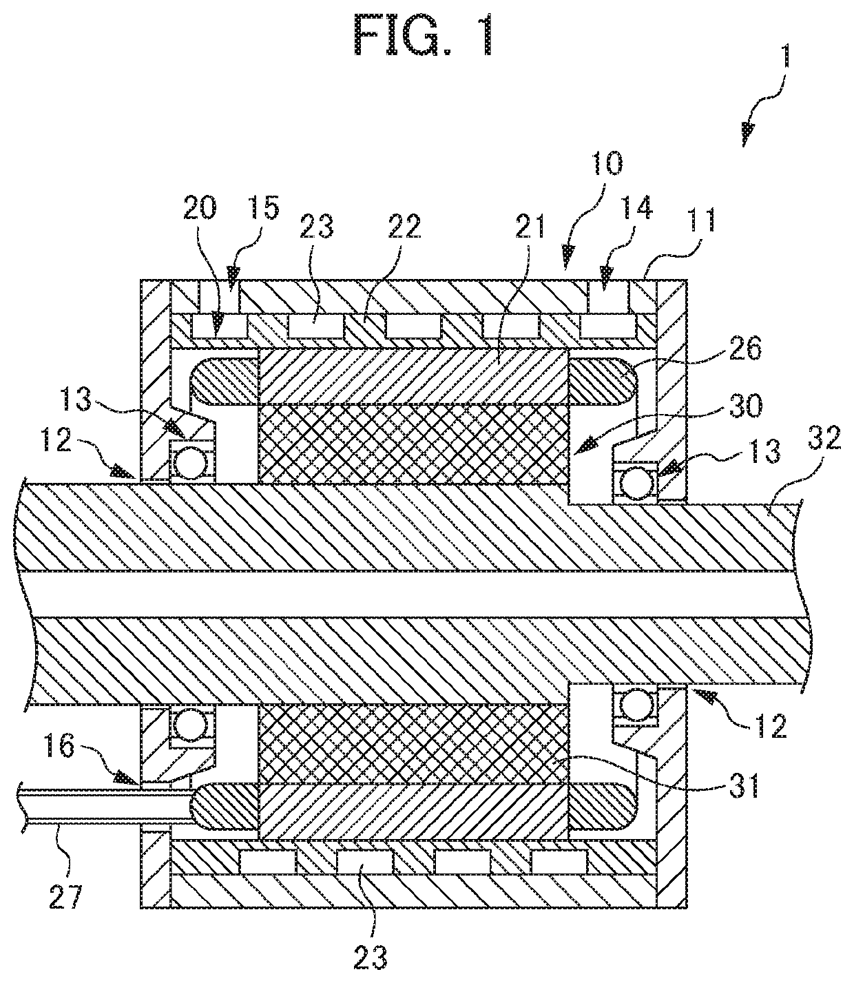
[0028]A motor 1 as a rotary electric machine including a stator of a first embodiment will be described first. FIG. 1 is a sectional view explaining the configuration of the motor 1 of the first embodiment. The configuration of the motor 1 shown in FIG. 1 is an example. The motor 1 may have any configuration as long as the stator of the present invention is applicable to the motor 1.

[0029]As shown in FIG. 1, the motor 1 includes a frame 10, a stator 20, and a rotor 30. The frame 10 is an exterior component of the motor 1 and includes a frame body 11, an axis hole 12, and a bearing 13. The frame body 11 is a housing that surrounds and holds the stator 20. The frame body 11 holds the rotor 30 through the bearing 13. The frame body 11 includes a supply port 14, a discharge port 15, and a hole part 16. The supply port 14 is an opening for supply of a coolant to a flow path 23 (described later) of a stator frame 22 and is connected to a supply pipe for the coolant (not shown in the drawi...

second embodiment

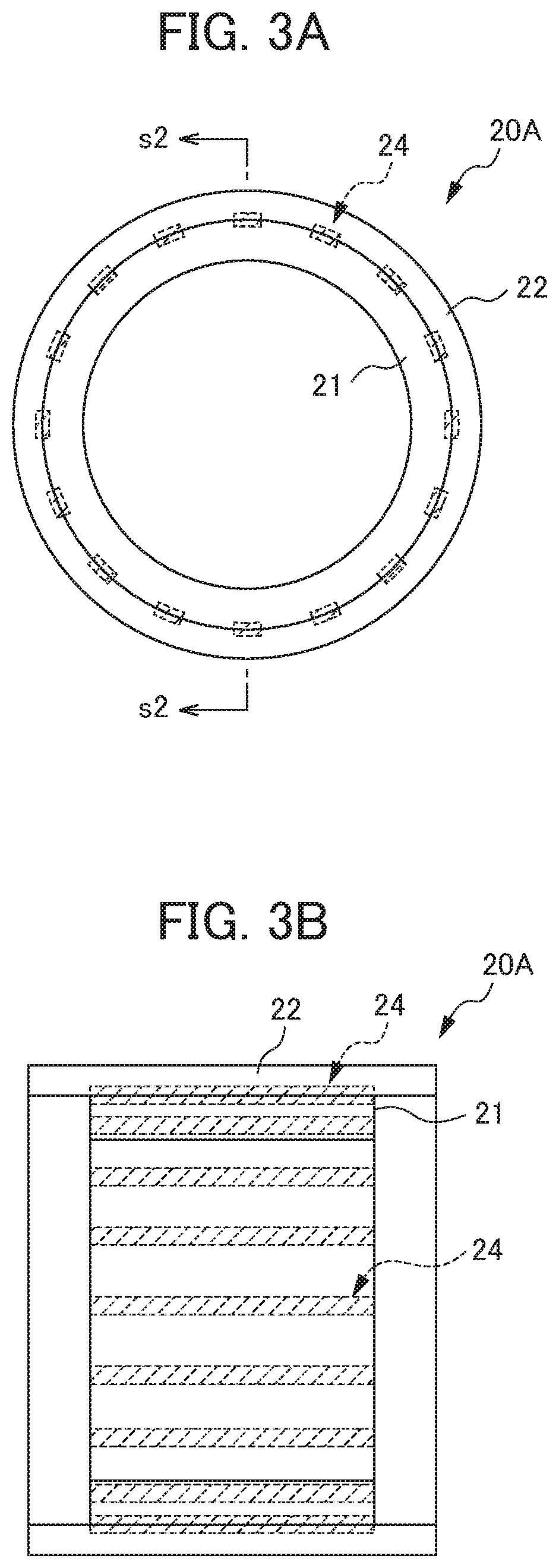
[0050]A stator 20A of a second embodiment will be described next. FIG. 3A shows the stator 20A of the second embodiment viewed from the axis direction. FIG. 3B is a sectional view taken along s2-s2 of FIG. 3A. The stator 20A of the second embodiment differs from the first embodiment in that multiple joints 24 are formed discontinuously at a boundary where the outer lateral surface of the core 21 and the inner lateral surface of the stator frame 22 are in contact with each other. The other structures of the stator 20A of the second embodiment are equal to those of the first embodiment. Thus, in the description and drawings of the second embodiment, a structure such as a member comparable to that of the first embodiment will be explained and illustrated by being given the same sign as in the first embodiment, and overlapping descriptions will not be given.

[0051]As shown in FIGS. 3A and 3B, in the stator 20A of the second embodiment, the outer lateral surface of the core 21 and the inn...

third embodiment

[0054]A stator 20B of a third embodiment will be described next. FIG. 4A shows the stator 20B of the third embodiment viewed from the axis direction. FIG. 4B is a sectional view taken along s3-s3 of FIG. 4A. Like the second embodiment, the stator 20B of the third embodiment differs from the first embodiment in that multiple joints 24 are formed discontinuously at a boundary where the outer lateral surface of the core 21 and the inner lateral surface of the stator frame 22 are in contact with each other. The other structures of the stator 20B of the third embodiment are equal to those of the first embodiment. Thus, in the description and drawings of the third embodiment, a structure such as a member comparable to that of the first embodiment will be explained and illustrated by being given the same sign as in the first embodiment, and overlapping descriptions will not be given.

[0055]As shown in FIGS. 4A and 4B, in the stator 20B of the third embodiment, the outer lateral surface of t...


PUM


Abstract

A stator includes: a substantially cylindrical core allowing arrangement of a winding inside the core; and a stator frame joined to the outer lateral surface of the core through a joint. The joint is formed at least at a part of a boundary where the outer lateral surface of the core and the inner lateral surface of the stator frame are in contact with each other. A material forming the core and a material forming the stator frame are mixed at the joint.

Description

[0001]This application is based on and claims the benefit of priority from Japanese Patent Application No. 2017-106715, filed on May 30, 2017, the content of which is incorporated herein by reference.BACKGROUND OF THE INVENTIONField of the Invention[0002]The present invention relates to a stator and a rotary electric machine including the stator.Related Art[0003]In a rotary electric machine including a rotor and a stator, the stator is constructed of a core in which a winding is arranged, and a stator frame attached to the outer lateral surface of the core. The core is required to be fixed tightly to the stator frame in order to receive counterforce generated by the torque of the rotor. A method called hot-fitting is known as one of methods or fixing the core to the stator frame. Hot-fitting is a method by which the stator frame is thermally expanded by heating in order to increase the inner diameter of the stator frame, the core is fitted into the stator frame, and then the stator ...

Claims


Application Information

Patent Timeline
Patent Type & Authority Patents(United States)
IPC IPC(8): H02K9/22H02K3/12H02K15/02H02K3/34H02K5/18H02K9/00H02K15/14
CPCH02K15/026H02K3/12H02K5/18H02K9/005H02K3/345H02K9/22H02K15/14H02K1/185H02K9/227H02K9/223H02K9/00
Inventor TAKANO, SHINOBU
Owner FANUC LTD
Why Eureka
Try Eureka