
X-ray generation tube, X-ray generation apparatus, and X-ray imaging apparatus

a technology of x-ray generation and x-ray imaging, which is applied in the direction of x-ray tubes, x-ray tube gas control, television systems, etc., can solve the problems of unstable x-ray focal dimension, and achieve the effect of reducing the x-ray focal dimension

Active Publication Date: 2020-11-17
CANON ANELVA CORP
View PDF10 Cites 4 Cited by
  • Summary
  • Abstract
  • Description
  • Claims
  • Application Information

AI Technical Summary

Benefits of technology

The present invention provides an X-ray generation tube with a stable X-ray focal dimension, achieved by using an opening limiting element to reduce the X-ray focal dimension. The distal end of the focusing electrode has a lower thermal conductivity than the second portion, which ensures a stable X-ray focal dimension. This invention also provides an X-ray generation apparatus with the X-ray generation tube and a driving circuit, and an X-ray imaging apparatus with the X-ray generation apparatus and an X-ray detection apparatus.

Problems solved by technology

However, when an opening limiting element as described above is provided in the X-ray generation tube to reduce the X-ray focal dimension, a new problem that the X-ray focal dimension is not stable arises.

Method used


Image

  • X-ray generation tube, X-ray generation apparatus, and X-ray imaging apparatus
  • X-ray generation tube, X-ray generation apparatus, and X-ray imaging apparatus
  • X-ray generation tube, X-ray generation apparatus, and X-ray imaging apparatus

Examples


first embodiment

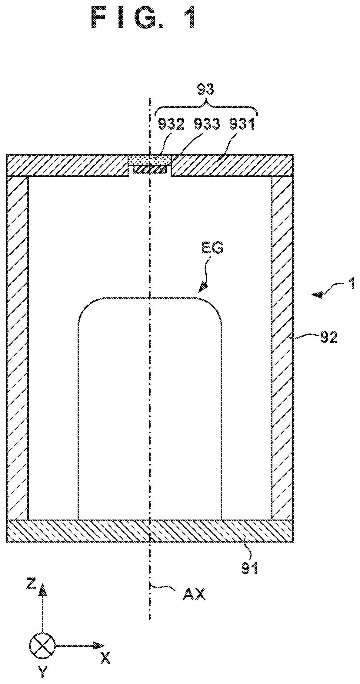
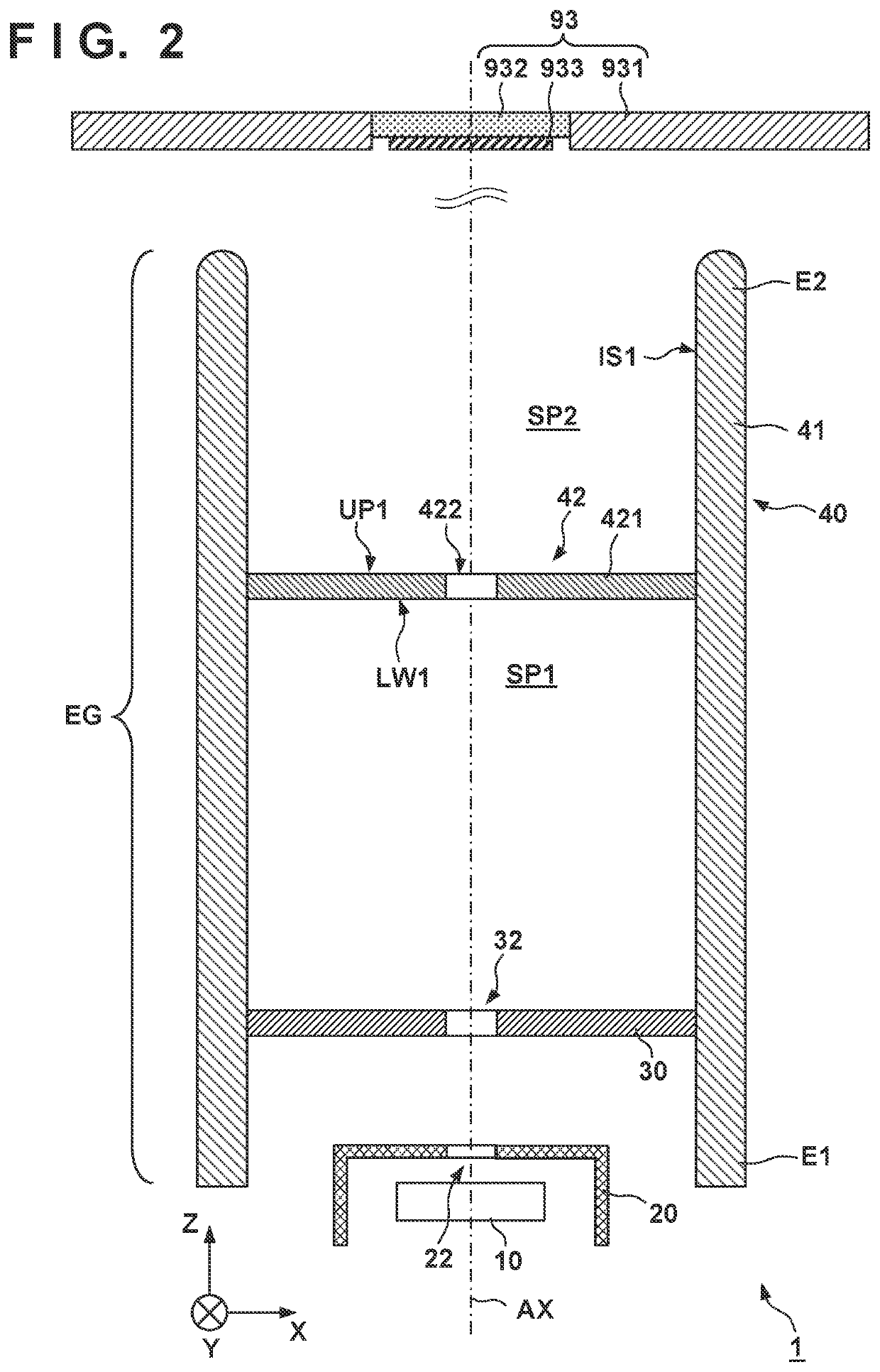
[0018]FIG. 2 schematically shows the arrangement of the X-ray generation tube 1 according to the present invention. FIG. 2 shows the electron gun EG and the anode 93 which are arranged close. However, the electron gun EG and the anode 93 can be arranged farther apart. The electron gun EG can include a cathode 10 including an electron emitting portion that emits electrons, an extraction electrode 30 that extracts the electrons emitted from the electron emitting portion, and a focusing electrode 40 that focuses the electrons extracted by the extraction electrode 30. The cathode 10 can include, for example, an oxide cathode, an impregnated type cathode, a hot filament, or the like as the electron emitting portion. The electrons can be emitted when the cathode 10 is heated. The extraction electrode 30 includes a passage hole 32 through which electrons pass. The electron gun EG may include a gate electrode 20 between the cathode 10 and the extraction electrode 30. The gate electrode 20 i...

second embodiment

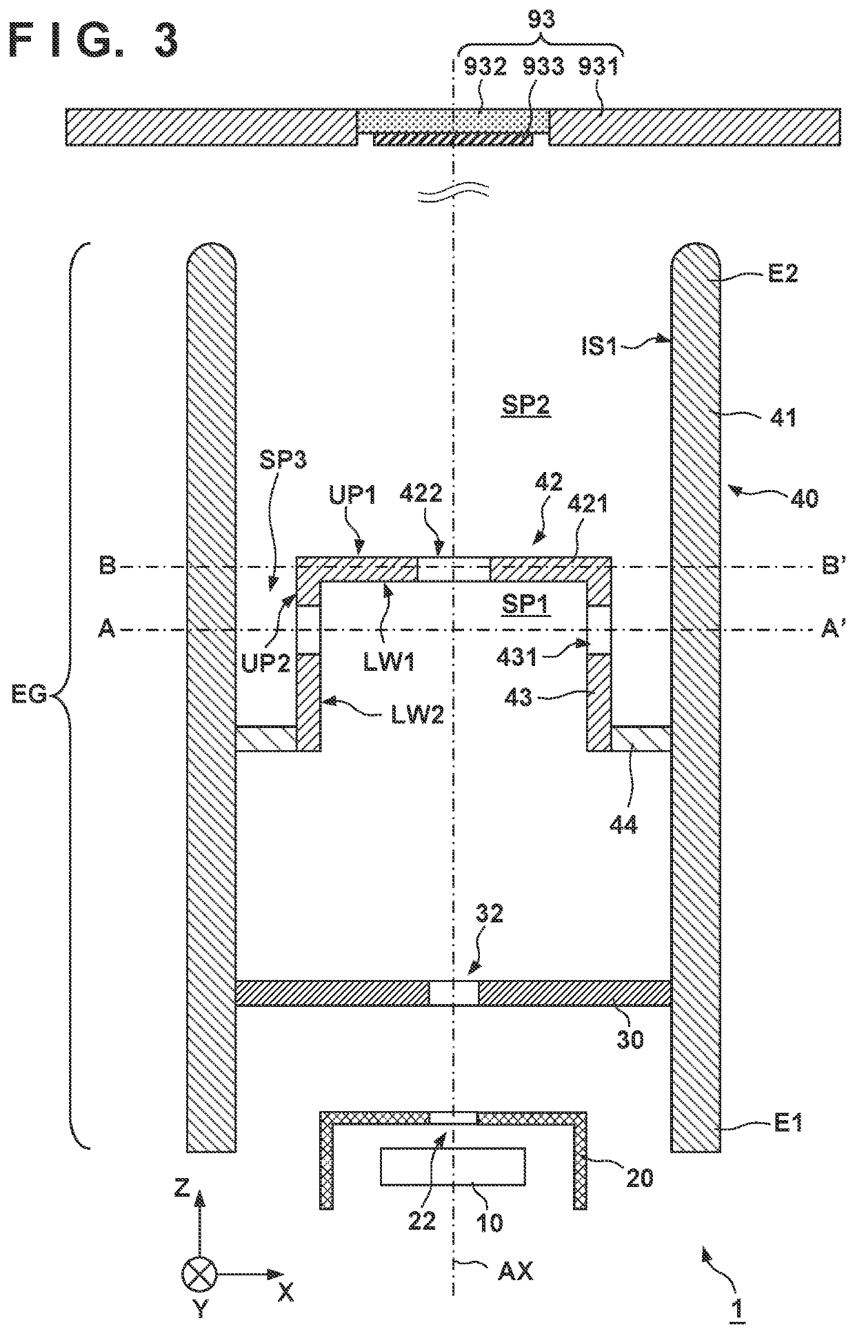
[0036]To prevent this, in the electron gun EG the communicating portion 431 that makes the first space SP1 and the second space SP2 communicate is provided in the second portion 42. The communicating portion 431 can be arranged at a position where the electrons do not become incident on it or at a position where the possibility of incidence of the electrons is low. In another viewpoint, the communicating portion 431 can be arranged at a position where the electrons do not pass. The communicating portion 431 allows the gas that can be generated in the first space SP1 to be quickly discharged from the first space SP1 to the second space SP2. This functions to suppress degradation of the cathode 10.

[0037]The focusing electrode 40 may be formed such that a linear path via the communicating portion 431 exists between the inside surface IS1 of the first portion 41 and a region of the plate portion 421 where the electrons can collide. Alternatively, the focusing electrode 40 may be formed...


PUM


Abstract

X-ray generation tube includes electron gun, and anode having target to generate X-rays upon collision with electrons from the electron gun. The electron gun includes cathode having electron emitting portion, extraction electrode to extract the electrons from the electron emitting portion, and focusing electrode to focus the extracted electrons. The focusing electrode includes first portion having tubular shape, and second portion arranged inside the first portion. The first portion includes distal end facing the anode, the second portion includes opposing surface facing the anode, and the opposing surface includes electron passage hole through which the electrons from the electron emitting portion pass. Distance between the distal end and the anode is shorter than that between the opposing surface and the anode. Thermal conductivity of the distal end is lower than that of the second portion.

Description

CROSS-REFERENCE TO RELATED APPLICATION[0001]This application is a continuation of International Patent Application No. PCT / JP2019 / 024986 filed on Jun. 24, 2019, the entire disclosure of which is incorporated herein by reference.TECHNICAL FIELD[0002]The present invention relates to an X-ray generation tube, an X-ray generation apparatus, and an X-ray imaging apparatus.BACKGROUND ART[0003]An X-ray generation apparatus is used in, for example, an X-ray imaging apparatus that captures a subject by X-rays. PTL 1 describes an X-ray generation tube that generates X-rays. The X-ray generation tube described in PTL 1 includes a cathode, a target, a first control grid arranged between the cathode and the target, and a second control grid arranged between the first control grid and the target. The second control grid includes an opening limiting element that suppresses spread of an electron beam. When the opening limiting element is provided, the electron beam dimension can be reduced.CITATION...

Claims


Application Information

Patent Timeline
IPC IPC(8): H01J35/06H04N5/32H01J35/08
CPCH04N5/32H01J35/064H01J35/08H01J35/147H01J2235/20H01J35/186H04N23/30H01J35/14H05G1/10
Inventor TSUJINO, KAZUYA
Owner CANON ANELVA CORP
Learn More