Field emission electron gun

a field emission electron and electron gun technology, applied in the direction of oscillator generators, electric discharge tubes, electrical equipment, etc., can solve the problems of unsatisfactory power supplies, adverse effects on inability to achieve correct focusing, so as to improve resolution and image quality of electron microscope images, enhance analytical accuracy, and reduce the amount of scattered electrons hitting the specimen surface

Inactive Publication Date: 2007-05-03
JEOL LTD
View PDF1 Cites 4 Cited by
  • Summary
  • Abstract
  • Description
  • Claims
  • Application Information

AI Technical Summary

Benefits of technology

[0012] It is an object of the present invention to provide a field emission electron gun (FEG) which can improve the resolution and image quality of electron microscope images and enhance the analytical accuracy by greatly reducing the amount of scattered electrons hitting a specimen surface.

Problems solved by technology

In a cold FEG, these power supplies are unnecessary.
Because the focusing conditions imposed by an electron lens located behind the acceleration electrode are different from those for electrons with accelerating voltage VA, correct focusing is not achieved.
In the state of FIG. 7b, the resolution and image quality of electron microscope images are adversely affected.

Method used


Image

  • Field emission electron gun
  • Field emission electron gun
  • Field emission electron gun

Examples


Embodiment Construction

[0025] Embodiments of the present invention are hereinafter described with reference with the accompanying drawings.

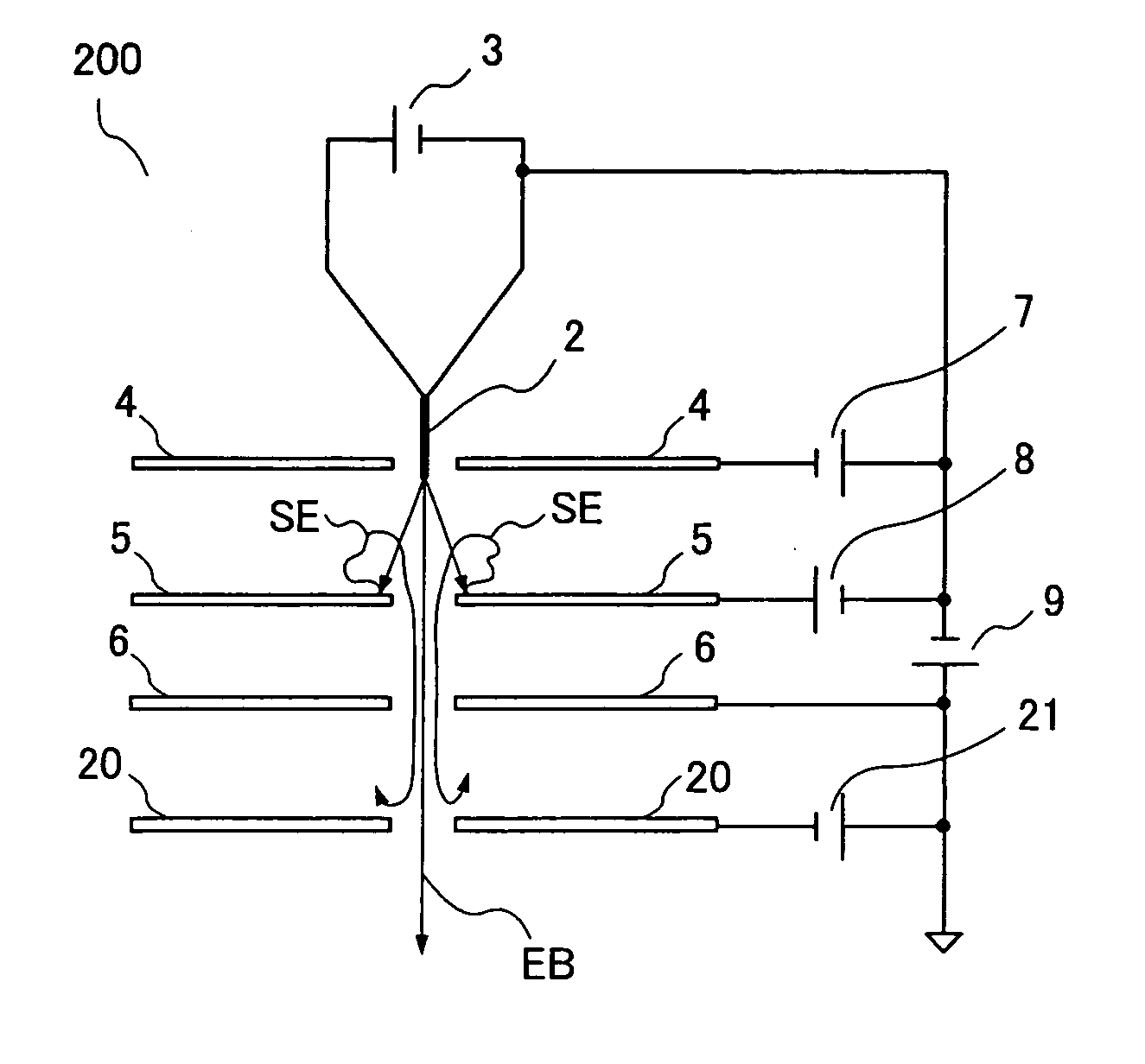
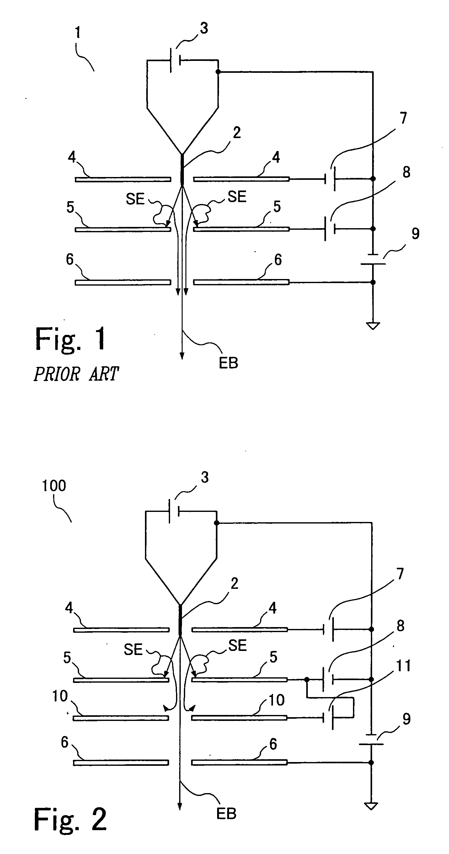
[0026]FIG. 2 schematically shows the structure of an electron gun 100 for carrying out the present invention. It is to be noted that like components are indicated by like reference numerals in both FIGS. 1 and 2 and that those components which have already been described will not be described below. In FIG. 2, a repeller electrode 10 is disposed between the extractor electrode 5 and the acceleration electrode 6. A repeller power supply 11 is mounted to apply a given voltage to the repeller electrode 10.

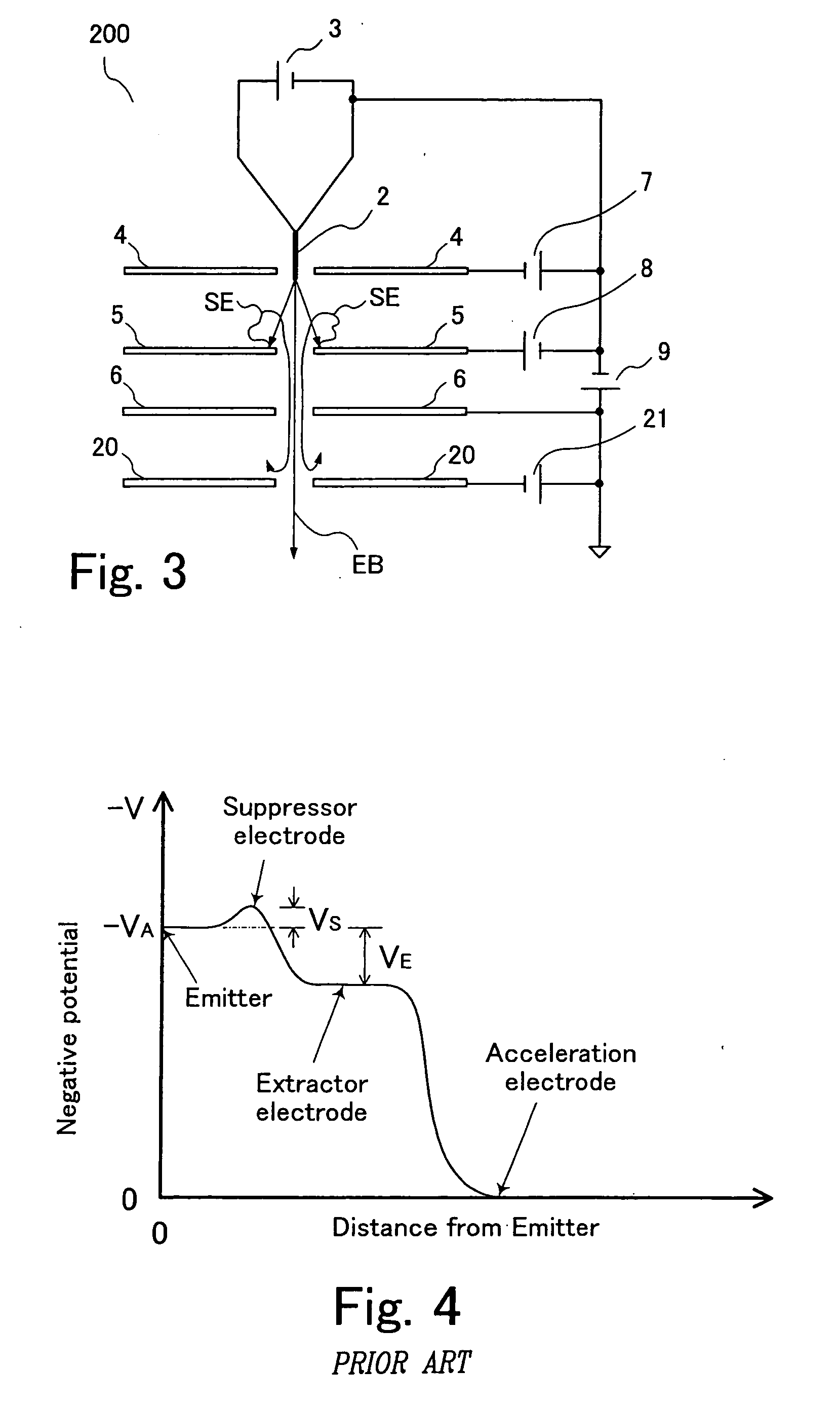
[0027]FIG. 5 is a graph illustrating the relationship between the electrodes and potentials in the electron gun 100. In the same way as in FIG. 4, the vertical axis indicates the potential (−V) on the optical axis of the electron beam EB. The negatively increasing direction is in the upward direction. The horizontal axis indicates the distance from the emitter, taken a...


PUM


Abstract

Electron beam equipment fitted with a field emission electron gun (FEG) having an extractor electrode, an acceleration electrode, a repeller electrode disposed between the extractor electrode and the acceleration electrode, and a repeller power supply for applying a given voltage to the repeller electrode. Electrons extracted from the emitter collide against the extractor electrode, producing secondary electrons moving toward the acceleration electrode. The secondary electrons are repelled by the repeller electrode and thus prevented from reaching the specimen.

Description

BACKGROUND OF THE INVENTION [0001] 1. Field of the Invention [0002] The present invention relates to a field emission electron gun (also known as a field emission gun (FEG)) installed in an electron microscope or other similar instrument. More particularly, the invention relates to a field emission gun improved such that the amount of scattered electrons hitting a specimen surface is greatly reduced. [0003] 2. Description of Related Art [0004] Because an FEG emits an electron beam having a quite narrow energy width and provides high brightness, the FEG is suitable for improvement of performance in terms of imaging and analysis. Therefore, FEGs are used in many electron beam instruments typified by electron microscopes. An FEG has an emitter for emitting electrons and an extractor electrode. A voltage is applied between the emitter and the extractor electrode to extract electrons from the emitter by a strong electric field formed at the tip of the emitter. FEGs are classified into th...

Claims


Application Information

Patent Timeline
Patent Type & Authority Applications(United States)
IPC IPC(8): H03B9/06
CPCH01J37/073H01J2237/06316
Inventor KUDOH, MASATOKONDOH, YUKIHITO
Owner JEOL LTD
Why Eureka
Try Eureka