Foundry core

a technology of foundry cores and cores, applied in the field of foundry cores, can solve the problems of large-scale technical, difficult rapid-clocked series manufacturing of foundry cores of the type in question, and only possible removal of cores from the core shooting machine, etc., and achieve the effect of cost-effective and time-saving

Active Publication Date: 2020-11-24
NEMAK S A B DE
View PDF12 Cites 0 Cited by
  • Summary
  • Abstract
  • Description
  • Claims
  • Application Information

AI Technical Summary

Benefits of technology

[0023]“Spatially separated” and “physically independently” in this context means that for each of the sub-segments one suitably-mould cavity is in each case provided in a core shooting machine. This of course includes the possibility important in practice of shaping the sub-segments together and simultaneously in a core shooting box in which a mould cavity is provided for each of the sub-segments. This variant of the method according to the invention allows a cost-effective and time-saving manufacture of respectively one set of sub-segments, which can be composed together to form a foundry core according to the invention.

Problems solved by technology

The particular challenge with the manufacture of foundry cores of the type in question here is that the foundry cores generally do not form a solid body, but rather are interrupted at multiple points such that their walls form finely broken-down structures, which can comprise islands, in which larger quantities of core materials are collected, larger and thicker tracks, finely branched webs, larger bridges and other delicately shaped forming elements.
Owing to the circumferentially closed base structure of the foundry cores typically circular or ellipsoidal in cross-section, the removal of the cores from the core shooting machine is only possible with significant effort with such finely broken-down foundry cores.
Aside from the high costs involved with such complex machines, this complexity makes a large-scale technical, quickly-clocked series manufacture of foundry cores of the type in question here more difficult.

Method used


Image

  • Foundry core
  • Foundry core
  • Foundry core

Examples


Embodiment Construction

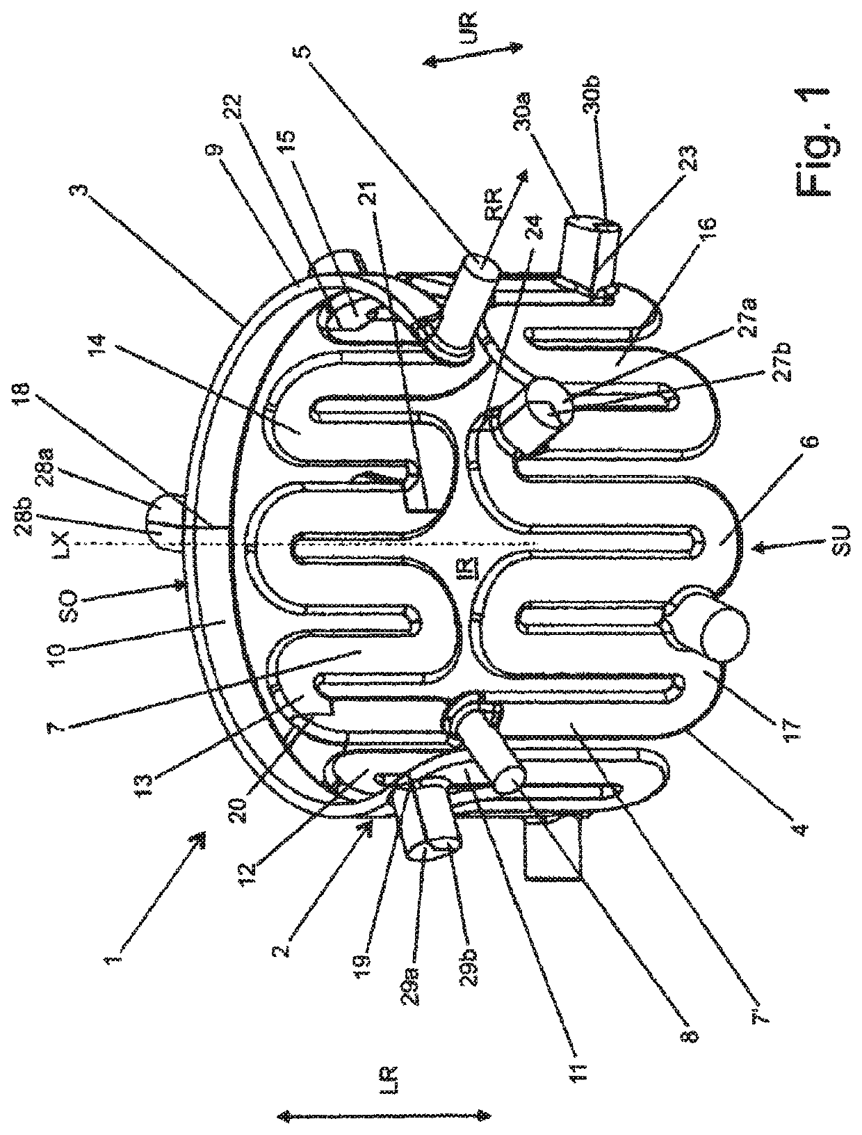
[0028]The foundry core 1 has the base form of a cylindrical hollow body and accordingly delimits an interior IR, which extends in the longitudinal direction LR from the lower end face SU to the upper end face SO of the foundry core 1.

[0029]The foundry core 1 shaped from a moulding material proven for this purpose and mixed from a forming sand and an organic or inorganic binder in a manner known per se serves to represent a cooling water sheath in a housing for an electric motor serving as a vehicle drive, which is cast in a casting mould, not illustrated further here and for example composed as a core packet, made of a light metal melt, such as for example of a conventional aluminium cast material.

[0030]The circumferential wall 2 of the foundry core 1 is formed by an annular segment-shaped annular section 3 circulating around the longitudinal axis LX of the foundry core 1 and a meander section 4.

[0031]Proceeding from a projection 5 protruding outwards in the radial direction RR and ...


PUM


Abstract

The present invention relates to a foundry core, which has the base form of a hollow body, with the foundry core being formed from a moulding material consisting of a mixture which is formed from a moulding sand and a binder and optionally from additives added to set its properties and a method for its manufacture. The foundry core according to the invention can be easily manufactured. This is achieved as a result of the foundry core being divided into at least two sub-segments and forming elements interacting with one another in a positive-locking manner being provided on the edge sides, with which sub-segments arranged adjacent to one another abut on one another, or in proximity to these edge sides, via which forming elements the sub-segments arranged adjacent to one another are fixed by positive locking immovably against one another at least in one direction.

Description

CROSS-REFERENCE TO RELATED APPLICATIONS[0001]This application is the United States national phase of International Application No. PCT / IB2018 / 000316 filed Mar. 28, 2018, and claims priority to German Patent Application No. 10 2017 106 775.2 filed Mar. 29, 2017, the disclosures of which are hereby incorporated by reference in their entirety.BACKGROUND OF THE INVENTIONField of the Invention[0002]The invention relates to a foundry core, which has the base form of a hollow body, with the foundry core being shaped from a moulding material consisting of a mixture which is formed from a moulding sand and a binder and optionally from additives added to set its properties.Description of Related Art[0003]Foundry cores of the type in question here serve for the foundry-related manufacture of cast parts made of a metal melt. In the respective cast part, the foundry cores form cavities, such as channels or chambers. These cavities can be provided to save weight. However, a fluid generally flows ...

Claims


Application Information

Patent Timeline
Patent Type & Authority Patents(United States)
IPC IPC(8): B22C9/10
CPCB22C9/108B22C9/103B22C21/14
Inventor BARANZKE, MATTHIASSTAUDT, INGO
Owner NEMAK S A B DE
Why Eureka
Try Eureka