Optical scanner and imaging apparatus
a scanning and optical technology, applied in the field of optical scanners, can solve the problems of limited downsizing of the actuator and a device mounted with the actuator, unstable operation of the actuator, and unstable common electrodes, so as to reduce the number of electrical wirings, maintain the stability of the operation, and reduce the size of the entire apparatus
- Summary
- Abstract
- Description
- Claims
- Application Information
AI Technical Summary
Benefits of technology
Problems solved by technology
Method used
Image
Examples
embodiment 1
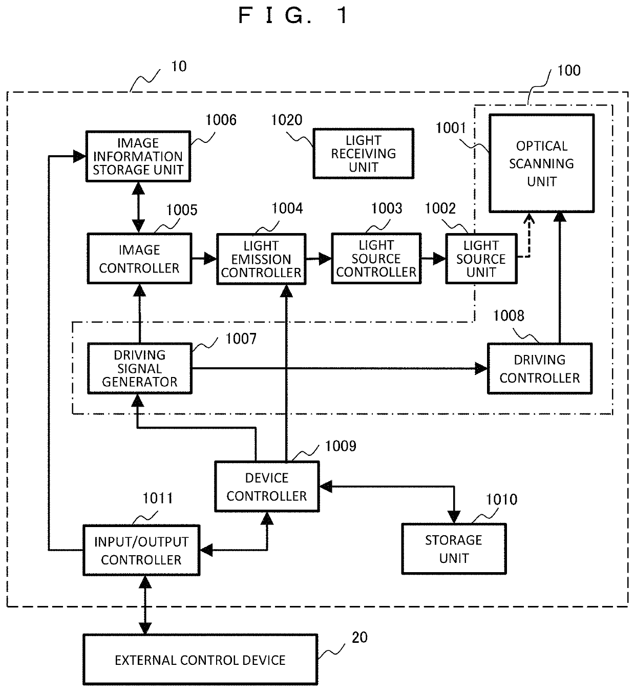
[0027]FIG. 1 is a block diagram illustrating a configuration of an imaging apparatus 10 according to Embodiment 1. For example, the imaging apparatus 10 is an apparatus that projects an image such as a projector or a head mounted display, and includes an optical scanner 100 that scans image light on a projection surface.
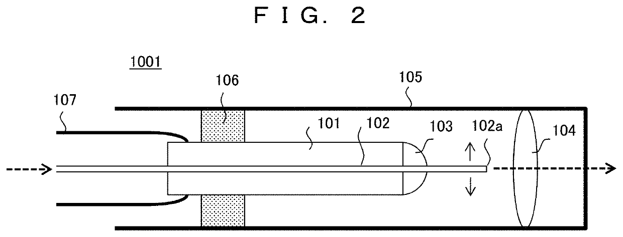
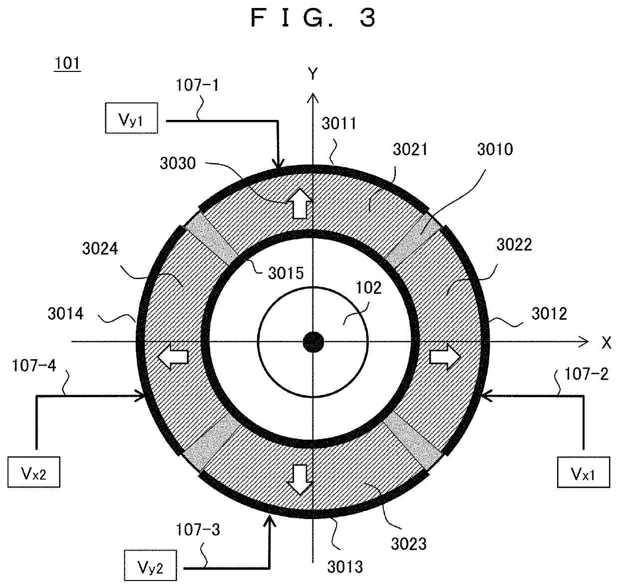
[0028]The imaging apparatus 10 includes an optical scanning unit 1001, a light source unit 1002, a light source controller 1003, a light emission controller 1004, an image controller 1005, an image information storage unit 1006, a driving signal generator 1007, a driving controller 1008, a device controller 1009, a storage unit 1010, an input / output controller 1011, and a light receiving unit 1020. Among these units, the optical scanning unit 1001, and the driving signal generator 1007 and the driving controller 1008 driving the optical scanning unit 1001 are included in the optical scanner 100. Incidentally, the optical scanner 100 may include another element such a...
embodiment 2
[0076]In Embodiment 1, all the impedances of the four piezoelectric elements are equal to each other. However, in practice, the impedances may not coincide with each other due to a manufacturing variation, etc. Therefore, Embodiment 2 adopts a configuration in which a driving signal is corrected in accordance with an impedance difference.
[0077]FIG. 9 is a block diagram illustrating a configuration of an imaging apparatus 10 according to Embodiment 2. The apparatus is configured such that a driving signal correction unit 1012 is added to the basic configuration of Embodiment 1 (FIG. 1).
[0078]The driving signal correction unit 1012 corrects a driving signal according to minute differences in the impedances of the four piezoelectric elements included in the vibration portion 101. That is, a driving signal obtained by correcting the amplitude of the driving signal generated by the driving signal generator 1007 is supplied to the driving controller 1008. Hereinafter, a description will b...
embodiment 3
[0085]In Embodiment 1, the waveform of the driving signal of the piezoelectric element has a sinusoidal shape. However, in Embodiment 3, a pulse-like driving signal is used.
[0086]FIG. 11 is a block diagram illustrating a configuration of an imaging apparatus 10 according to Embodiment 3. The apparatus is configured such that a driving pulse generator 1017 and a driving controller 1018 replace corresponding units of the basic configuration of Embodiment 1 (FIG. 1). The driving pulse generator 1017 generates a driving pulse as a driving signal, and the driving controller 1018 applies a drive voltage to the optical scanning unit 1001 (the vibration portion 101) based thereon.
[0087]FIGS. 12A-12B are diagrams illustrating a configuration example of the driving controller 1018. Here, a gate circuit such as an H bridge circuit is used. As a switching element, FIG. 12A uses a MOSFET and FIG. 12B uses a transistor. Here, a driving circuit in which a voltage is applied to the pair of piezoele...
PUM
 Abstract
Description
Claims
Application Information
 - R&D
- Intellectual Property
- Life Sciences
- Materials
- Tech Scout
- Unparalleled Data Quality
- Higher Quality Content
- 60% Fewer Hallucinations
Browse by: Latest US Patents, China's latest patents, Technical Efficacy Thesaurus, Application Domain, Technology Topic, Popular Technical Reports.
© 2025 PatSnap. All rights reserved.Legal|Privacy policy|Modern Slavery Act Transparency Statement|Sitemap|About US| Contact US: help@patsnap.com


