Automatic detection and positioning of pole-like objects in 3D

a technology applied in the field of automatic detection and positioning of polelike objects in 3d, can solve the problems of large blind spots, application requirements that require greater accuracy than, and additional challenges for the environment in improving this accuracy

Active Publication Date: 2020-11-24
HERE GLOBAL BV
View PDF12 Cites 1 Cited by
  • Summary
  • Abstract
  • Description
  • Claims
  • Application Information

AI Technical Summary

Problems solved by technology

However, some applications require greater accuracies than obtainable with GPS, even with enhanced accuracy techniques.
Localization techniques that match a location to a map or environment face additional challenges in improving this accuracy.
When used alone though, on-board sensor systems may exhibit large blind spots and may be unable to predict events or maneuvers even a short distance away.
However, due to the scanning pattern of current 3D sensors, distant objects produce more sparse point cloud data readings compared to closer objects.
In autonomous vehicle applications, the point cloud data from roadside objects are so sparse that it is often not possible to compute reliable statistics for each point of the point cloud data.
The technical problem of existing techniques is that when the point cloud data is sparse, there are not enough data points for the existing techniques to accurately compute certain point features and detect the presence of pole-like objects.
This may result in incorrectly excluding points from further processing in certain sparse areas, even though the area may contain pertinent structures, such as pole-like objects, along the roadway that would be useful for the various applications mentioned above.
Because of the sparse and un-organized nature of LiDAR data, there are many such pole-like object candidates.
The point cloud data assigned to corresponding grid cells in a 2D occupancy grid may be limited depending on the methods used for collecting the point cloud data.
Determining the occupancy of a particular grid cell based on the point cloud data assigned to that particular grid cell may also be limited by a predetermined threshold number of point cloud data points.
Voxels for a 3D space containing large amounts of point cloud data points require a vast amount of storage space and bandwidth in order to be processed and communicated in a mobile system.
Thus, detecting pole-like objects in the 3D space and modeling these objects as cylinder features to represent roadside objects greatly reduces the storage and / or bandwidth requirements, since this representation keeps most of the relevant information useful for localization while massively reducing the data size as compared to modeled features based on voxels of a 3D occupancy grid containing large amount of data points.
Not having horizontal slices 132 that cover both sides of the region of the roadway 131 may result in missing data associated with the region of the roadway 131, which in turn may have negative consequences for vehicle applications and result in unsafe operation of vehicles, particularly with assisted driving applications.
A higher resolution (smaller voxel size) may lead to more cluster detections in the output, but not all of them may be actual pole-like objects, which results in a lower precision ratio.
A smaller resolution (larger voxel size) may lead to less cluster detections in the output, but some true pole-like objects might be missed, which results in a higher precision, but lower recall ratio.
Additionally, the illustrations are merely representational and may not be drawn to scale.

Method used


Image

  • Automatic detection and positioning of pole-like objects in 3D
  • Automatic detection and positioning of pole-like objects in 3D
  • Automatic detection and positioning of pole-like objects in 3D

Examples


embodiment 1

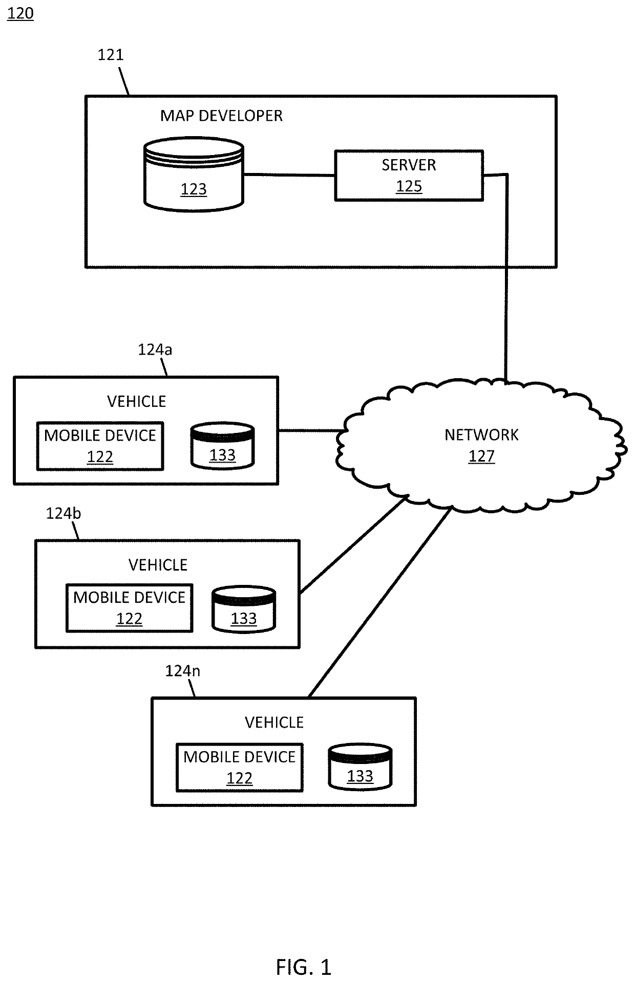
A method for automatically detecting pole-like objects for a location along a region of a roadway, the method comprising:

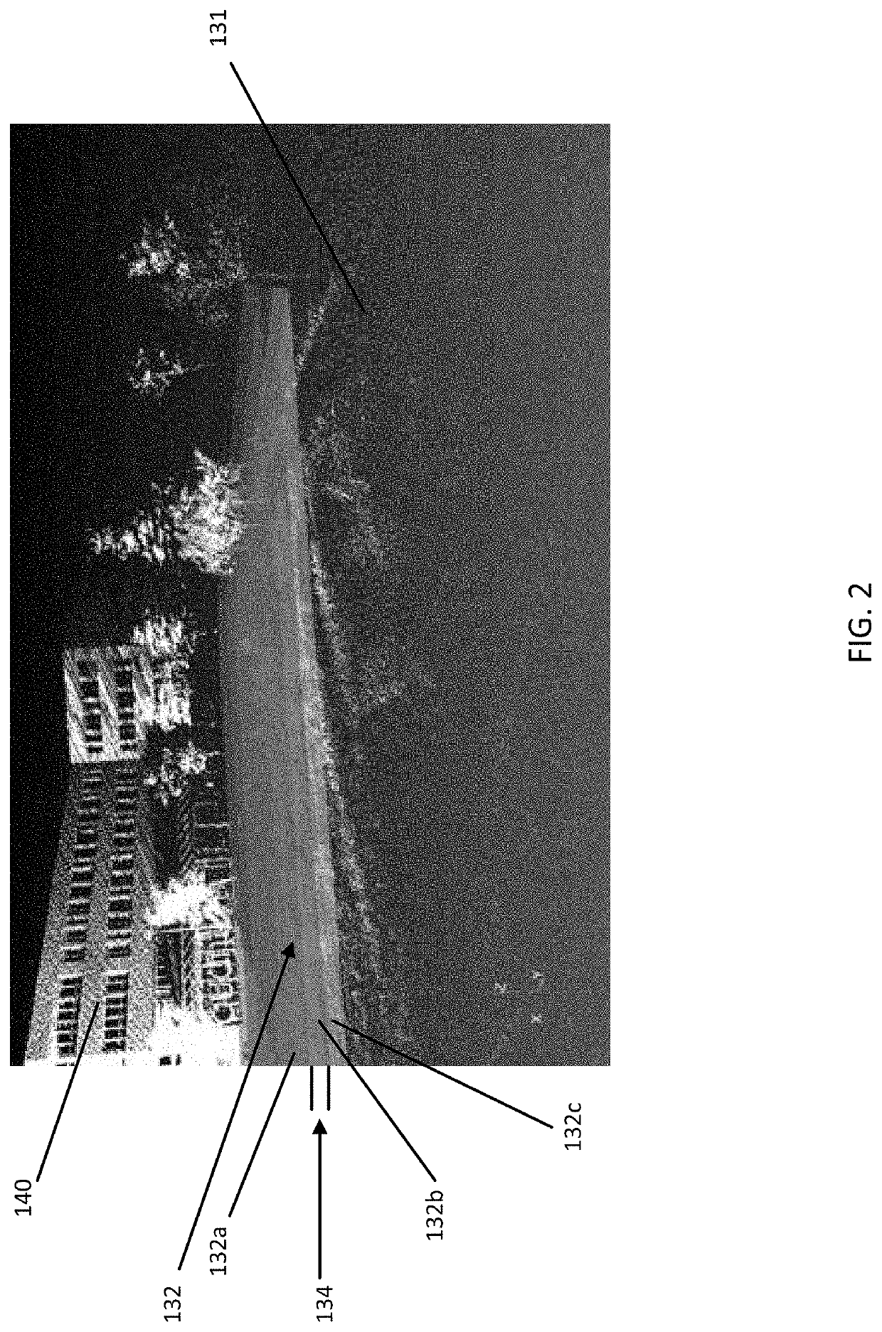
[0148]receiving, by a processor, point cloud data associated with the location along the region of a roadway;

[0149]identifying, by the processor, horizontal slices of point cloud data based on a predetermined horizontal slice thickness or a predetermined resolution;

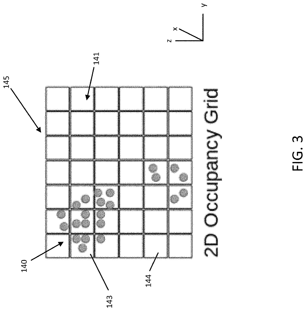
[0150]generating, by the processor, two-dimensional (2D) occupancy images for the horizontal slices of point cloud data, wherein a 2D occupancy image for a horizontal slice of point cloud data represents a finite height of point cloud data;

[0151]detecting, by the processor, vertical clusters of point cloud data based on the 2D occupancy images;

[0152]determining, by the processor, whether the vertical clusters of point cloud data represent pole-like objects; and

[0153]modeling, by the processor, the vertical clusters of point cloud data as cylinders.

embodiment 2

The method of embodiment 1, wherein identifying horizontal slices of point cloud data comprises:

[0154]associating the point cloud data to respective horizontal slices of point cloud data based on the predetermined horizontal slice thickness or resolution;

[0155]estimating point cloud data associated with a road surface at the location along the region of the roadway; and

[0156]excluding the point cloud data estimated to be associated with the road surface at the location along the region of the roadway from the horizontal slices of point cloud data.

embodiment 3

The method of embodiment 1 or 2, wherein generating the 2D occupancy images comprises:

[0157]assigning the point cloud data in respective horizontal slices of point cloud data to corresponding grid cells;

[0158]determining a grid cell occupancy for the grid cells;

[0159]generating 2D occupancy grids based on the determined grid cell occupancy for the grid cells; and

[0160]encoding the 2D occupancy grids as 2D occupancy images.


PUM


Abstract

Embodiments include apparatus and methods for automatic detection of pole-like objects for a location at a region of a roadway and automatic localization based on the detected pole-like objects. Pole-like objects are modeled as cylinders and the models are generated based on detected vertical clusters of point cloud data associated to corresponding regions along the region of the roadway. The modeled pole-like objects are stored in a database and associated with the region of the roadway. Sensor data from a user located at the region of the roadway is received. The pole-like object model is accessed and compared to the received sensor data. Based on the comparison, localization of the user located at the region of the roadway is performed.

Description

FIELD[0001]The following disclosure relates to the detection of vertical clusters of point cloud data associated with a vicinity of a roadway that represent pole-like objects at the vicinity of the roadway, and in addition, applications for localization at the vicinity of the roadway based on the detected pole-like objects.BACKGROUND[0002]The Global Positioning System (GPS) or another global navigation satellite system (GNSS) provides location information to a receiving device anywhere on Earth as long as the device has a substantial line of sight without significant obstruction to three or four satellites of the system. The GPS system is maintained and made available by the United States government. Originally, the government retained exclusive use of GPS. Over time increasing levels of accuracy of the GPS signals were made available to the public.[0003]Accuracy of the GPS system alone is about 50 feet or 15 meters. The accuracy may be augmented using secondary techniques or system...

Claims


Application Information

Patent Timeline
Patent Type & Authority Patents(United States)
IPC IPC(8): G06K9/00G06K9/46G06K9/62G06T7/73
CPCG06K9/00201G06K9/00791G06K9/4638G06K9/6215G06K9/6228G06T7/75G06K2009/6213G06T2207/10028G06T2207/30252G01C21/30G01S7/4808G06T7/73G06T2207/30261G05D1/0246G05D1/0274G05D2201/0213G01S17/931G01S17/89G06V20/64G06V20/56G06F18/22G06F18/211
Inventor OZKUCUR, NEZIH ERGINHE, FANGNINGDORIA, DAVIDANIL, ENGIN BURAK
Owner HERE GLOBAL BV
Why Eureka
Try Eureka