
Multi-channel integrated photonic wavelength demultiplexer

a wavelength demultiplexer and multi-channel technology, applied in the field of photonic devices, can solve the problem of prohibitive cost of fiber-optic communication by deploying optical fibers

Active Publication Date: 2020-12-08
X DEV LLC
View PDF23 Cites 6 Cited by
  • Summary
  • Abstract
  • Description
  • Claims
  • Application Information

AI Technical Summary

Benefits of technology

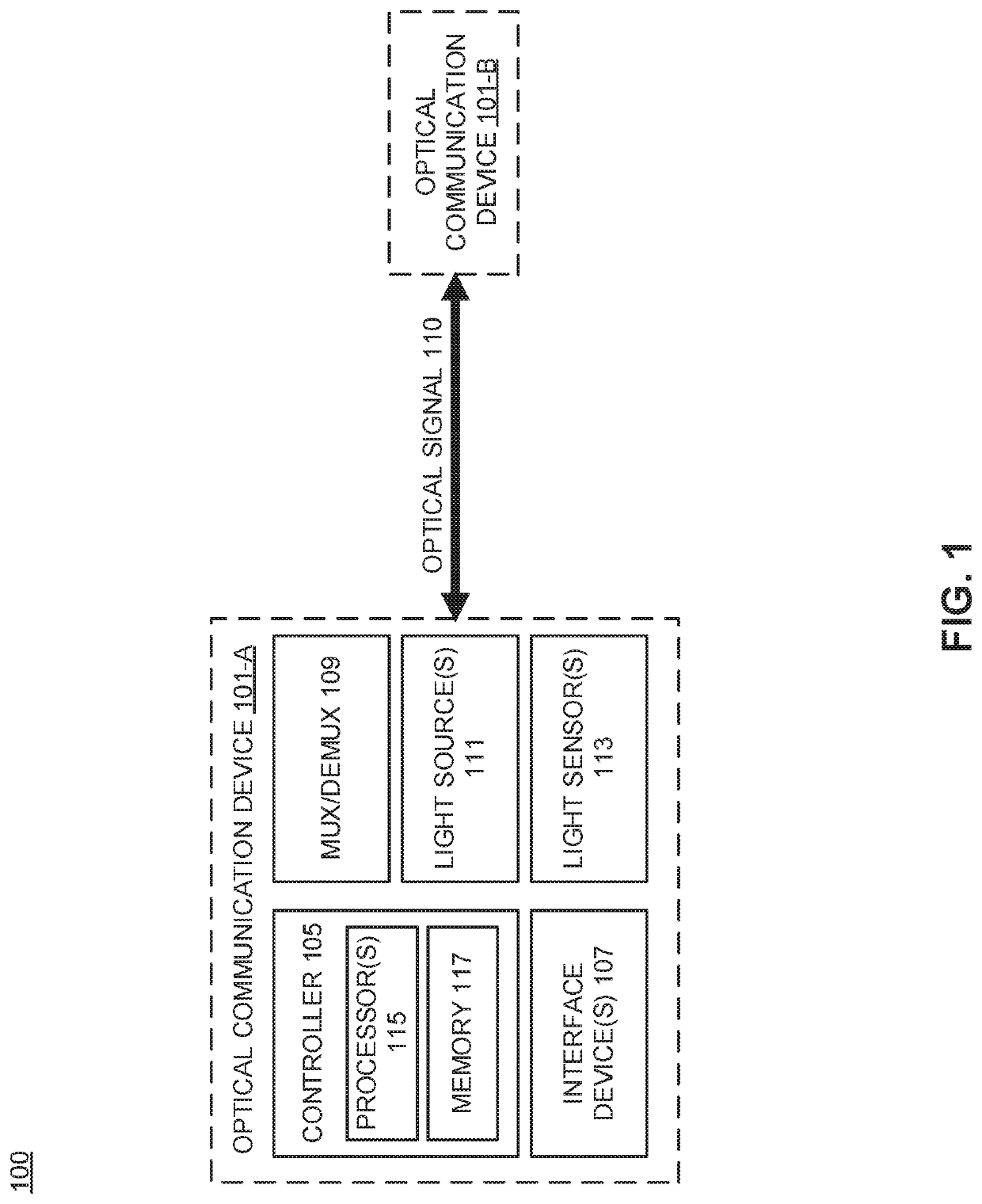
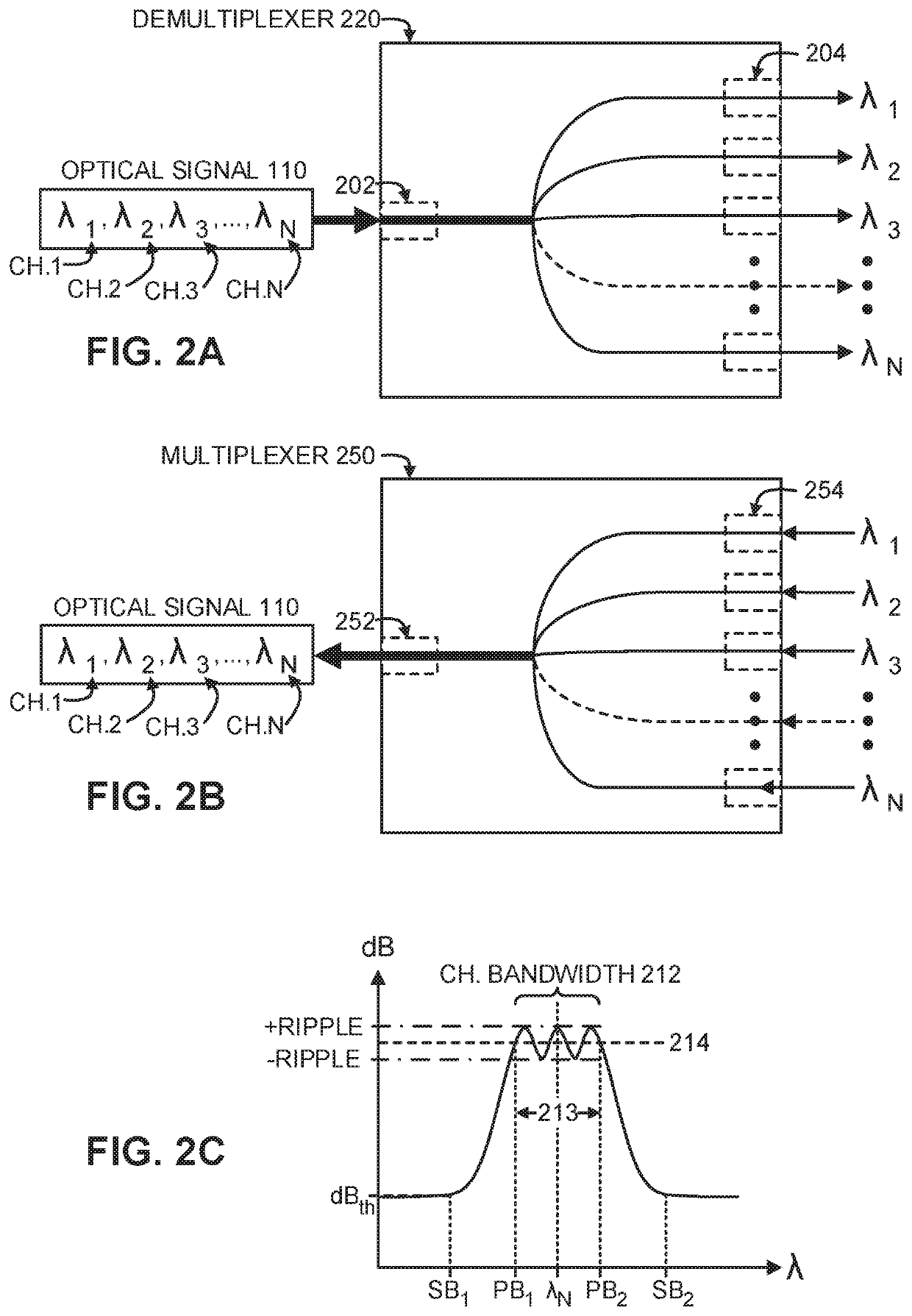
The patent text describes a system for optical communication using a multi-channel photonic demultiplexer and a method for generating a design of a photonic integrated circuit. The technical effects of the patent include the efficient use of bandwidth in optical fibers, the reduction of cost and size of devices that decouple carrier signals, and the improved design of photonic devices through a more automated process.

Problems solved by technology

But the cost of deploying optical fibers for fiber-optic communication may be prohibitive.

Method used


Image

  • Multi-channel integrated photonic wavelength demultiplexer
  • Multi-channel integrated photonic wavelength demultiplexer
  • Multi-channel integrated photonic wavelength demultiplexer

Examples


Embodiment Construction

[0016]Embodiments of photonic integrated circuits, including a multi-channel photonic demultiplexer, as well as a method for generating a design of photonic integrated circuits are described herein. In the following description numerous specific details are set forth to provide a thorough understanding of the embodiments. One skilled in the relevant art will recognize, however, that the techniques described herein can be practiced without one or more of the specific details, or with other methods, components, materials, etc. In other instances, well-known structures, materials, or operations are not shown or described in detail to avoid obscuring certain aspects.

[0017]Reference throughout this specification to “one embodiment” or “an embodiment” means that a particular feature, structure, or characteristic described in connection with the embodiment is included in at least one embodiment of the present invention. Thus, the appearances of the phrases “in one embodiment” or “in an emb...


PUM


Abstract

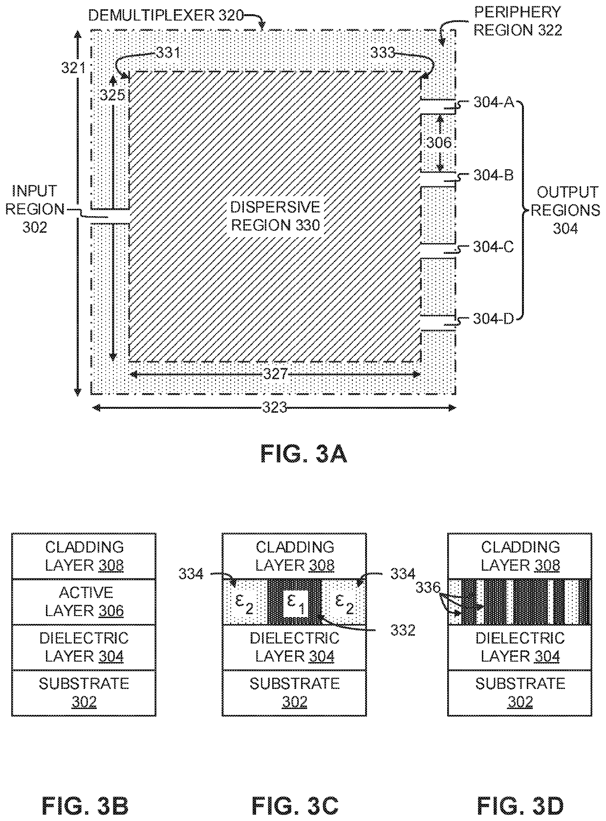
A multi-channel photonic demultiplexer includes an input region to receive a multi-channel optical signal including four distinct wavelength channels, four output regions, each adapted to receive a corresponding one of the four distinct wavelength channels demultiplexed from the multi-channel optical signal, and a dispersive region optically disposed between the input region and the four output regions. The dispersive region includes a first material and a second material inhomogeneously interspersed to form a plurality of interfaces that each correspond to a change in refractive index of the dispersive region and collectively structure the dispersive region to optically separate each of the four distinct wavelength channels from the multi-channel optical signal and respectively guide each of the four distinct wavelength channels to the corresponding one of the four output regions.

Description

TECHNICAL FIELD[0001]This disclosure relates generally to photonic devices, and in particular but not exclusively, relates to optical multiplexers and demultiplexers.BACKGROUND INFORMATION[0002]Fiber-optic communication is typically employed to transmit information from one place to another via light that has been modulated to carry the information. For example, many telecommunication companies use optical fiber to transmit telephone signals, internet communication, and cable television signals. But the cost of deploying optical fibers for fiber-optic communication may be prohibitive. As such, techniques have been developed to more efficiently use the bandwidth available within a single optical fiber. Wavelength-division multiplexing is one such technique that bundles multiple optical carrier signals onto a single optical fiber using different wavelengths.BRIEF DESCRIPTION OF THE DRAWINGS[0003]Non-limiting and non-exhaustive embodiments of the invention are described with reference ...

Claims


Application Information

Patent Timeline
IPC IPC(8): H04J14/02G06F30/30H04B10/25G06F30/367
CPCH04B10/25G06F30/367G06F30/30H04J14/02G06F30/337G06F30/23H04B10/67
Inventor SCHUBERT, MARTINADOLF, BRIANLU, JESSE
Owner X DEV LLC
Learn More