
Method for demodulating wavelength of fiber grating by utilizing linear tilt filter

A technology of wavelength demodulation and optical fiber grating, which is applied in the direction of optical demodulation, instruments, light guides, etc., can solve the problems that affect the market promotion and development of optical fiber sensing systems, small grating capacity, high price of optical fiber sensing systems, etc., and achieve guarantee The effect of industrial safety production, precise demodulation accuracy, and low cost

Inactive Publication Date: 2011-08-31
SHANDONG UNIV
View PDF4 Cites 5 Cited by
  • Summary
  • Abstract
  • Description
  • Claims
  • Application Information

AI Technical Summary

Problems solved by technology

The high price of the optical fiber sensing system limits the application range and places of the optical fiber sensing system to a certain extent, and affects the market promotion and further development of the optical fiber sensing system. For example, the patent application number is CN200710038145. The patent of Fiber Bragg Grating High Temperature Sensing System belongs to this list
However, the simple hypotenuse filter demodulation method is cost-effective, but the capacity of the demodulated grating is small. For example, the patent with the application number 200920172889.6 and the invention name "Sensing Wavelength Demodulator Based on Triangular Spectrum Fiber Bragg Grating" is belongs to this column

Method used


Image

  • Method for demodulating wavelength of fiber grating by utilizing linear tilt filter
  • Method for demodulating wavelength of fiber grating by utilizing linear tilt filter
  • Method for demodulating wavelength of fiber grating by utilizing linear tilt filter

Examples


Embodiment 1

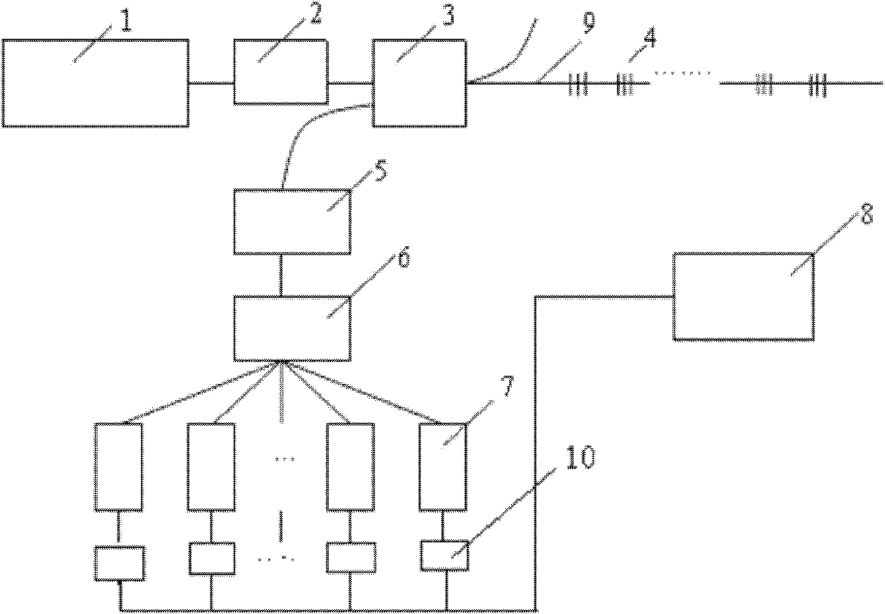
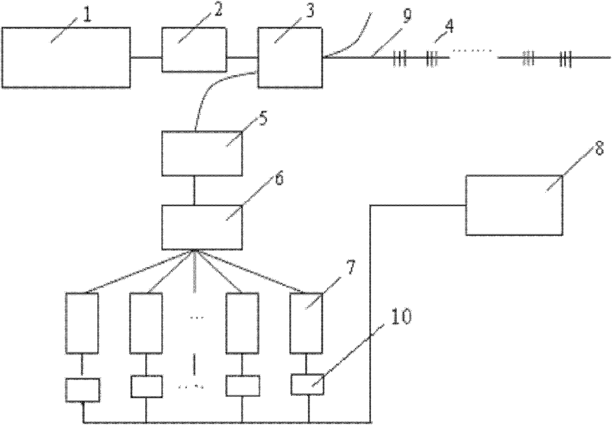
[0025] Embodiment 1 of the present invention such as figure 1 As shown, it includes ASE light source 1, isolator 2, 3dB coupler 3, FBG series 4, linear hypotenuse filter 5, wavelength demultiplexer 6, photodetector array 7, A / D converter 10, computer 8 and The optical fiber 9 is characterized in that the ASE light source 1 is located before the isolator 2, and a 3db coupler 3 is placed behind the isolator 2; the front end of the 3db coupler 3 is connected to the input end of the linear hypotenuse filter 5 through an optical fiber, and its rear end is passed through The output end of the optical fiber and a FBG series 4-connected linear hypotenuse filter 5 is connected with the wavelength demultiplexer 6 through the optical fiber, and the wavelength demultiplexer 6 is respectively connected with each photodetector 7 in the photodetector array through the optical fiber, The light of different wavelengths separated by the wavelength demultiplexer 6 is passed to the corresponding ...

Embodiment 2

[0028] Same as embodiment 1, except that the number of FBGs in the FBG series 4 and the number of photodetectors 7 in the photodetector array are 8 respectively.

Embodiment 3

[0030] Same as Embodiment 1, except that the numbers of FBGs and photodetectors 7 are 6 respectively.


PUM


Abstract

The invention relates to a method for demodulating the wavelength of a fiber grating by utilizing a linear tilt filter and belongs to the technical field of fiber grating wavelength demodulation. A device comprises an ASE (amplified spontaneous emission) light source, a 3db coupler, a fiber grating, the linear tilt filter, a wavelength demultiplexer, light intensity detection arrays and an A / D (analog to digital) converter, wherein the ASE light source is arranged in front of the 3db coupler; the fiber grating is arranged behind the 3db coupler; the 3db coupler is respectively connected to the linear tilt filter and the FBG (fiber bragg grating) through light guide fibers; the front end of the wavelength demultiplexer is connected to the linear tilt filter while the back end is connected to different light intensity detection arrays; and the light intensity detection arrays are electrically connected to a computer system through leads respectively, thereby realizing the wavelength demodulation through the computer. The device and method provided by the invention are low in cost, the monitoring method is simple and practical, and the device and method can be widely applied to various fields of production and living, such as temperature and stress monitoring.

Description

(1) Technical field [0001] The invention relates to a fiber grating wavelength demodulation method using a linear hypotenuse filter, specifically a fiber grating wavelength demodulation method using a linear hypotenuse filter, a wavelength demultiplexer and a photoelectric detection array, which belongs to the fiber grating Wavelength demodulation technology field. (2) Technical background [0002] When the wide-spectrum light is incident on the fiber grating, the light corresponding to the center wavelength of the fiber grating will be reflected back, and the center wavelength corresponding to the fiber grating will change with the external environment such as the temperature and stress of the fiber grating. This property of fiber gratings has been widely used in many fields of production and life, using fiber gratings as sensors for temperature, strain and other sensing systems. In the fiber optic sensing system, the value of the wavelength reflected by the fiber grating ...

Claims


Application Information

Patent Timeline
IPC IPC(8): G02F2/00G02B6/293
Inventor 孔德龙常军刘永宁宋复俊王宗良王伟杰张燕
Owner SHANDONG UNIV
Learn More