
Compact wavelength division multiplexer/demultiplexer

A wavelength division multiplexer and demultiplexer technology, applied in the direction of instruments, light guides, optics, etc., can solve the problem of increasing the sensitivity of the optical path, and achieve the effect of small size and simple structure

Inactive Publication Date: 2016-11-09
SUZHOU JIALAN ZHIYUAN ELECTRONICS TECH CO LTD
View PDF8 Cites 6 Cited by
  • Summary
  • Abstract
  • Description
  • Claims
  • Application Information

AI Technical Summary

Problems solved by technology

In order to realize light reflection in the medium, so as to realize decomposition or coupling, usually the incident and outgoing light will have a certain angle, such as there is a certain angle between 120 and 132 in the accompanying drawing of Chinese patent CN201280004164, and then For example, in the US patent US8538210B2, multiple optical glass blocks and excessive reflections in the optical path structure increase the sensitivity of the optical path in the product

Method used


Image

  • Compact wavelength division multiplexer/demultiplexer
  • Compact wavelength division multiplexer/demultiplexer

Examples


Embodiment Construction

[0017] Specific embodiments of the present invention will be further described in detail below.

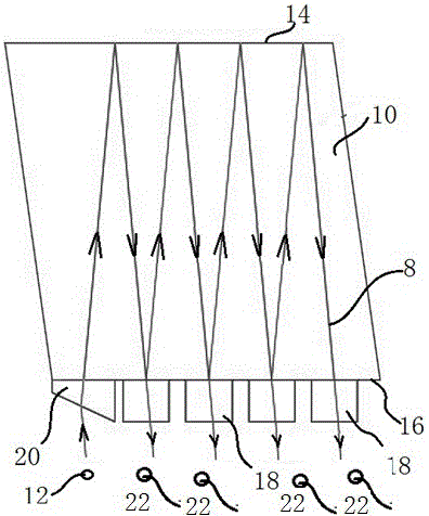
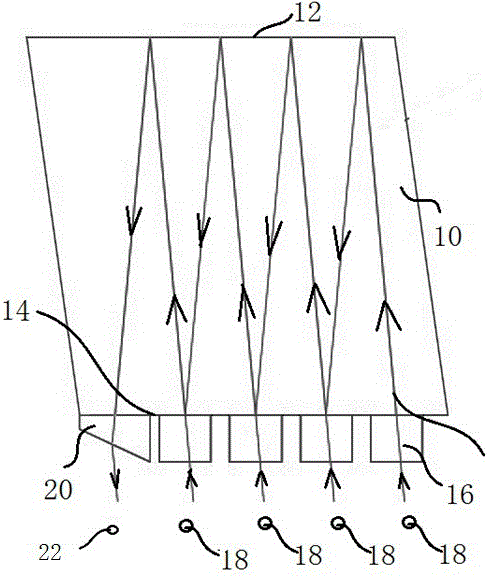
[0018] Such as figure 1 As shown, the present invention provides a compact wave demultiplexer, which includes an optical block 10 made of high light-transmitting glass, an input end 12 and an output end 22 . The optical block 10 includes a first side 14 and a second side 16 parallel to each other, wherein the first side 14 is coated with a high reflective film (not shown) and formed as a reflective surface for reflecting light. The second side 16 is provided with a plurality of filters 18 , respectively filtering light rays 8 of different wavelengths and reflecting light rays 8 of other wavelengths back. The light 8 emitted by the input end 12 is transmitted in the optical block 10, the light 8 is reflected between the first side 14 and the filter 18 to pass through all the filters 18 in turn, and the light passing through the filter 18 enters the output end 22 . A refracting p...


PUM

PropertyMeasurementUnit
Angleaaaaaaaaaa

Abstract

The invention discloses a compact wavelength division multiplexer and a compact wavelength demultiplexer. The compact wavelength division multiplexer and the compact wavelength demultiplexer both include an optical block, an input end and an output end, wherein the optical block includes a first side surface and a second side surface, wherein the first side surface is a reflecting surface which reflects light, and the second side surface is provided with a plurality of filters; light emitted by the input end is transmitted in the optical block; each time when the light is reflected to one filter, at least one part of the light passes through the filter, leaves the optical block and is emitted out through the output end; the second side surface is provided with a first refracting prism; light emitted from the input end is refracted by the refracting prism and enters the optical block; and an included angle between the light which is emitted from the input end and the light which passes through the filter is smaller than 20 degrees in the optical block. The compact wavelength division multiplexer and the compact wavelength demultiplexer of the invention have the advantages of simple structure, small size and the like.

Description

technical field [0001] The invention relates to a compact wave division multiplexer and a compact wave demultiplexer. Background technique [0002] In the same optical fiber, two or more optical wavelength signals are transmitted through different optical channels at the same time, which is called optical wavelength division multiplexing technology, or WDM for short. WDM is a communication technology that combines a series of information-carrying optical signals of different wavelengths into one bundle and transmits them along a single optical fiber; at the receiving end, a method is used to separate the optical signals of different wavelengths. Optical wavelength division multiplexing generally uses a wavelength division multiplexer and a demultiplexer (also called a multiplexer / demultiplexer) to be placed at both ends of the optical fiber to realize the coupling and separation of different light waves. With the development of technology, the requirements for miniaturizati...

Claims


Application Information

Patent Timeline
IPC IPC(8): G02B6/293
CPCG02B6/29373G02B6/2938
Inventor 赵泽雄毕延文余新文孙兴元
Owner SUZHOU JIALAN ZHIYUAN ELECTRONICS TECH CO LTD
Learn More