
Cavitation apparatus, configured to perform multiple simultaneous cavitations

a cavitation apparatus and cavitation chamber technology, applied in water/sludge/sewage treatment, water/sludge/sewage treatment, mixers, etc., can solve the problems of energy consumption, (s) may or may not allow access to the cavitation apparatus and its accessories, etc., to enhance the overall cavitation, accelerate and more powerful

Active Publication Date: 2020-12-15
ZUCCA TULLIA +1
View PDF5 Cites 2 Cited by
  • Summary
  • Abstract
  • Description
  • Claims
  • Application Information

AI Technical Summary

Benefits of technology

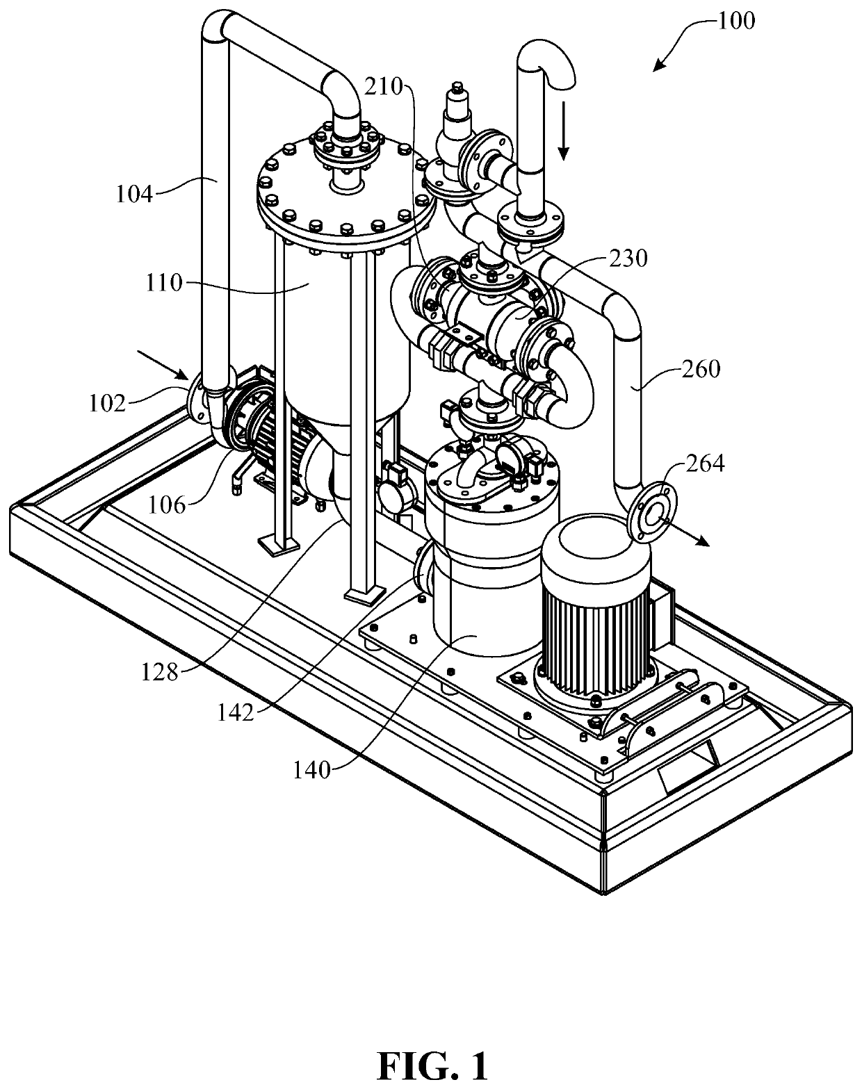
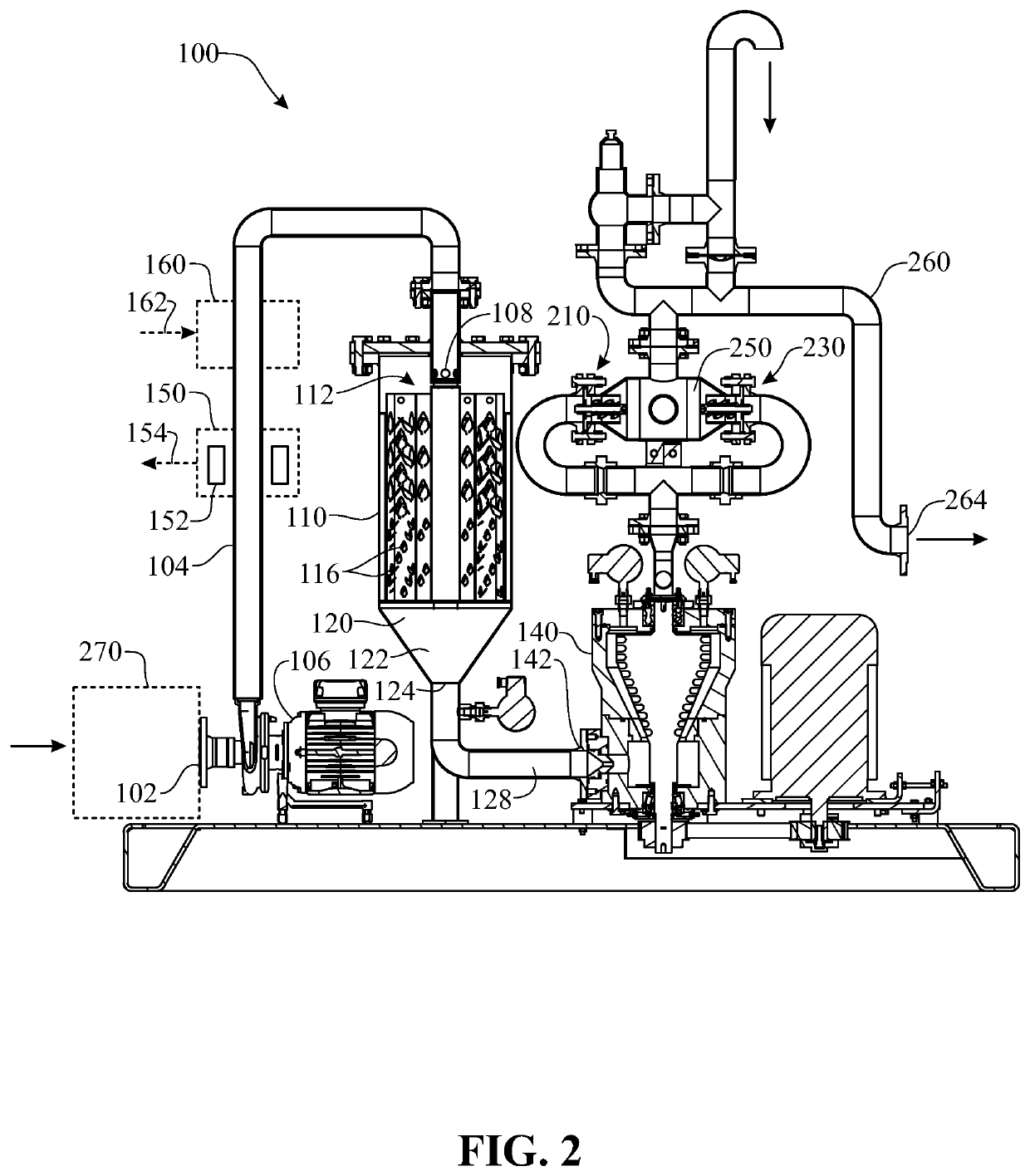
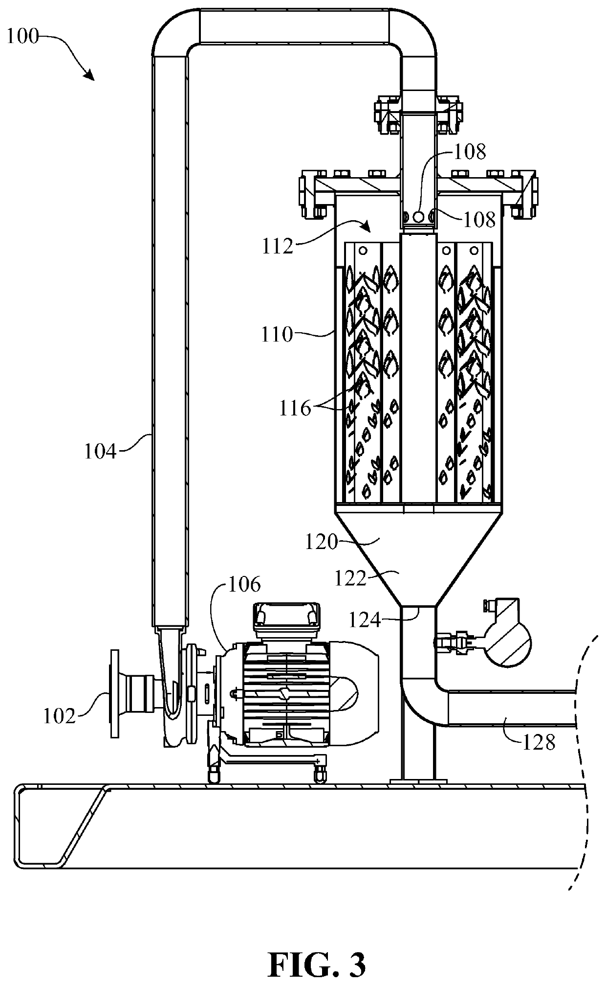
The present invention is a cavitation apparatus that can perform multiple, different-type cavitation processes simultaneously in the same geometric space, resulting in an effective cavitation process that is faster and more powerful than conventional apparatus. This synergy between the different cavitation processes allows for the modification of complex fluids, such as chemical, pharmaceutical, fuel, food and other industrial fluids, using the energy released upon the collapse of cavities in the flow. The apparatus can increase the efficiency of chemical, physical and biological processes, leading to higher yields in the same time frame and reducing the energy consumption required to obtain a certain quantity of product. The apparatus can also function as a pressure diffuser and polarize salts and polar molecules present in the fluid or other material passing through it.

Problems solved by technology

Further, incorporating the apparatus to an industrial process which produces a product may drastically reduce the energy consumption required to obtain a certain quantity of said product.
If placed in one or more containers, the container(s) may or may not allow access to the apparatus and its accessories or may allow limited access to components that require maintenance.

Method used


Image

  • Cavitation apparatus, configured to perform multiple simultaneous cavitations
  • Cavitation apparatus, configured to perform multiple simultaneous cavitations
  • Cavitation apparatus, configured to perform multiple simultaneous cavitations

Examples


Embodiment Construction

[0023]The following detailed description is merely exemplary in nature and is not intended to limit the described embodiments or the application and uses of the described embodiments. As used herein, the word “exemplary” or “illustrative” means “serving as an example, instance, or illustration.” Any implementation described herein as “exemplary” or “illustrative” is not necessarily to be construed as preferred or advantageous over other implementations. All of the implementations described below are exemplary implementations provided to enable persons skilled in the art to make or use the embodiments of the disclosure and are not intended to limit the scope of the disclosure, which is defined by the claims. For purposes of description herein, the terms “upper”, “lower”, “left”, “rear”, “right”, “front”, “vertical”, “horizontal”, and derivatives thereof shall relate to the invention as oriented in FIG. 1. Furthermore, there is no intention to be bound by any expressed or implied theo...


PUM


Abstract

A cavitation apparatus capable of performing multiple, different-type cavitation processes taking place simultaneously in the same geometric space, thereby obtaining an effective cavitation process that is significantly faster than those provided by conventional cavitation apparatus. The cavitation apparatus can include consecutive and / or simultaneous cavitation units which are configured to carry out consecutive and / or simultaneous cavitation processes on a material flowing through the apparatus, such that effects of one or more prior cavitation processes are present in the material while the material is subjected to one or more further cavitation processes within the apparatus, enhancing the cavitation effects in a reduced amount of time and increasing productivity of the apparatus. In some embodiments, the apparatus can perform seven cavitation processes, of four different types.

Description

FIELD OF THE INVENTION[0001]The present invention generally relates to a cavitation apparatus, and more particularly, to a cavitation apparatus which is capable of performing multiple, different-type cavitation processes taking place simultaneously in the same geometric space, thereby obtaining an effective cavitation process that is significantly faster than those provided by conventional cavitation apparatus.BACKGROUND OF THE INVENTION[0002]Cavitation is known since the late nineteenth century. Cavitation is a phenomenon which involves the rapid formation and implosion of cavities or bubbles in a low-pressure area in liquids. In general, cavitation is caused by applying forces onto a low-pressure liquid which cause the liquid pressure to drastically and rapidly drop, as a consequence of which the liquid vaporizes and cavities containing vapor are formed. When forces cease or the bubbles travel outside the area of the liquid which is being subjected to said forces, the vapor inside...

Claims


Application Information

Patent Timeline
IPC IPC(8): B01J19/00C02F11/00C02F1/34C02F9/00
CPCC02F1/34C02F11/00B01J19/008C02F9/00C02F2303/26B01F2025/913B01F25/23B01F25/4335B01F27/2723B01F27/2722B01F33/8212
Inventor ZUCCA, TULLIAVACCARI, BRUNO
Owner ZUCCA TULLIA
Learn More