
Inductors with compensated electromagnetic coupling

Active Publication Date: 2020-12-15
MARVELL ASIA PTE LTD
View PDF3 Cites 1 Cited by
  • Summary
  • Abstract
  • Description
  • Claims
  • Application Information

AI Technical Summary

Benefits of technology

This invention is about making electrical circuits with inductors that reduce interference with other components. The invention provides an inductor with coils that produce opposite magnetic fields that cancel out, minimizing interference. This design improves performance and reduces interference in, for example, voltage control oscillators and serializer / deserializer devices. It can be manufactured using existing semiconductor equipment and processes and can be used in existing devices for better performance.

Problems solved by technology

Integrating a complete RF transceiver on a single chip presents a number of challenges.
One of challenges is integrating multiple LC-VCOs configured to provide reference clock signals at different frequencies.
Unfortunately, existing inductors, as used in communication applications (e.g., as implemented in VCO circuits) are inadequate.

Method used


Image

  • Inductors with compensated electromagnetic coupling
  • Inductors with compensated electromagnetic coupling
  • Inductors with compensated electromagnetic coupling

Examples


Embodiment Construction

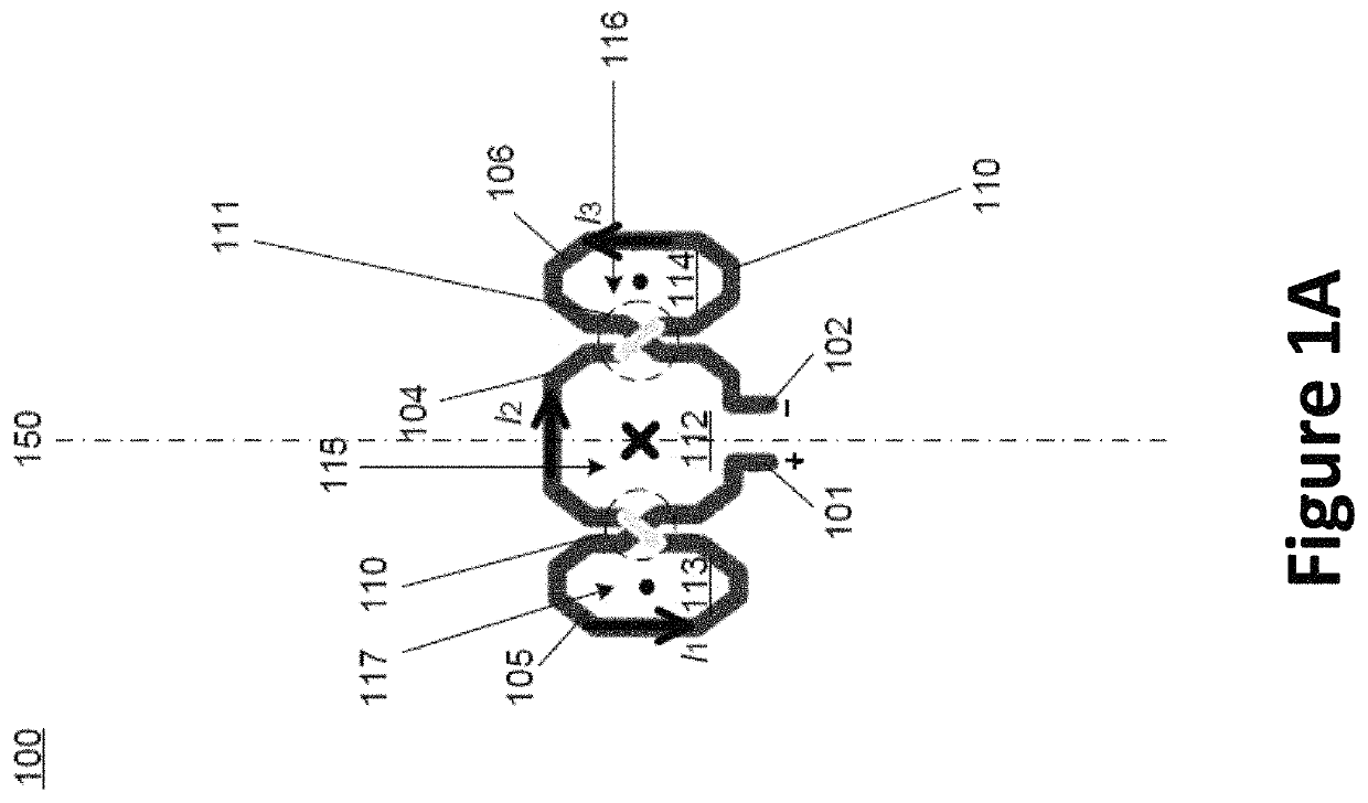
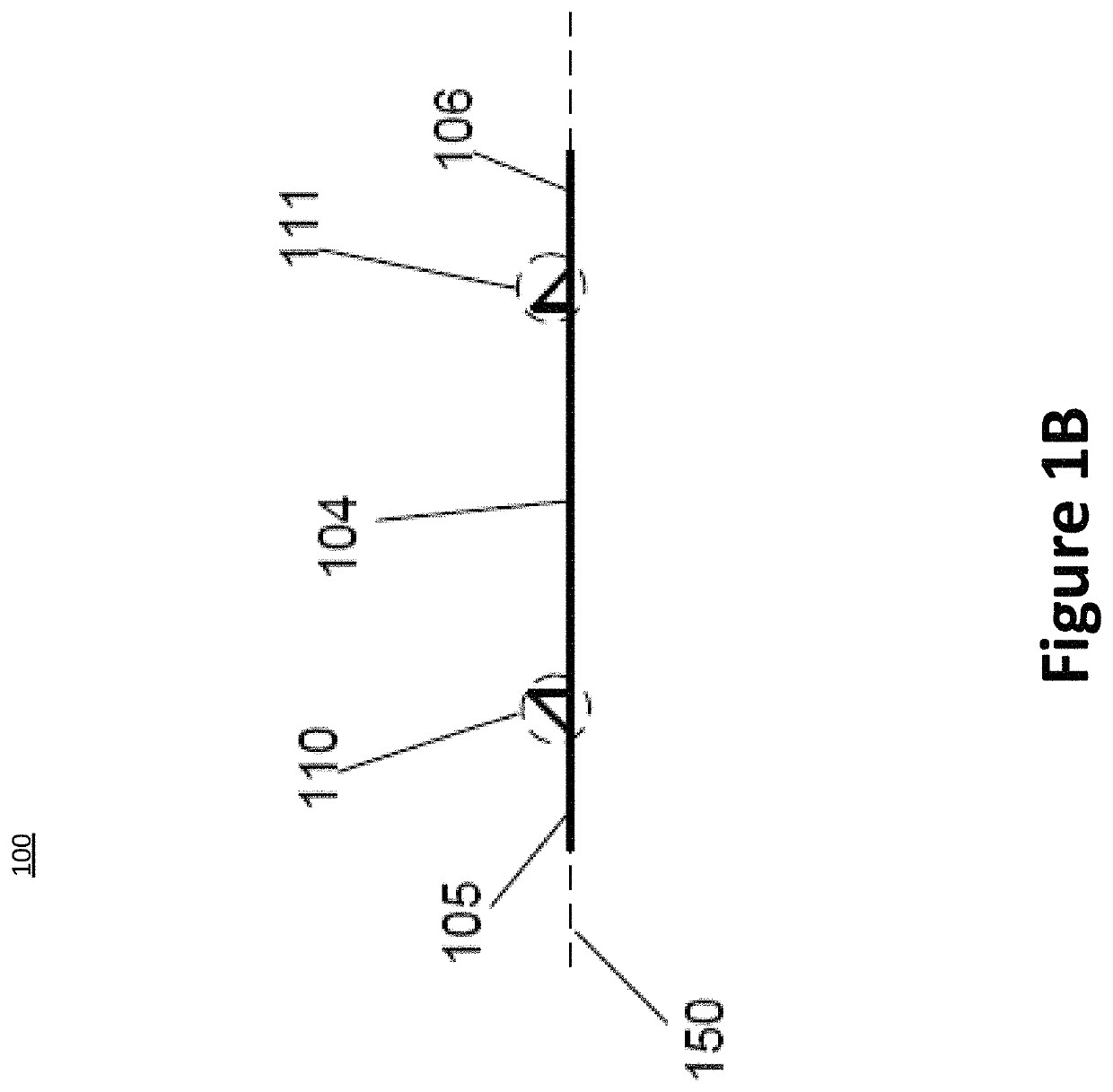
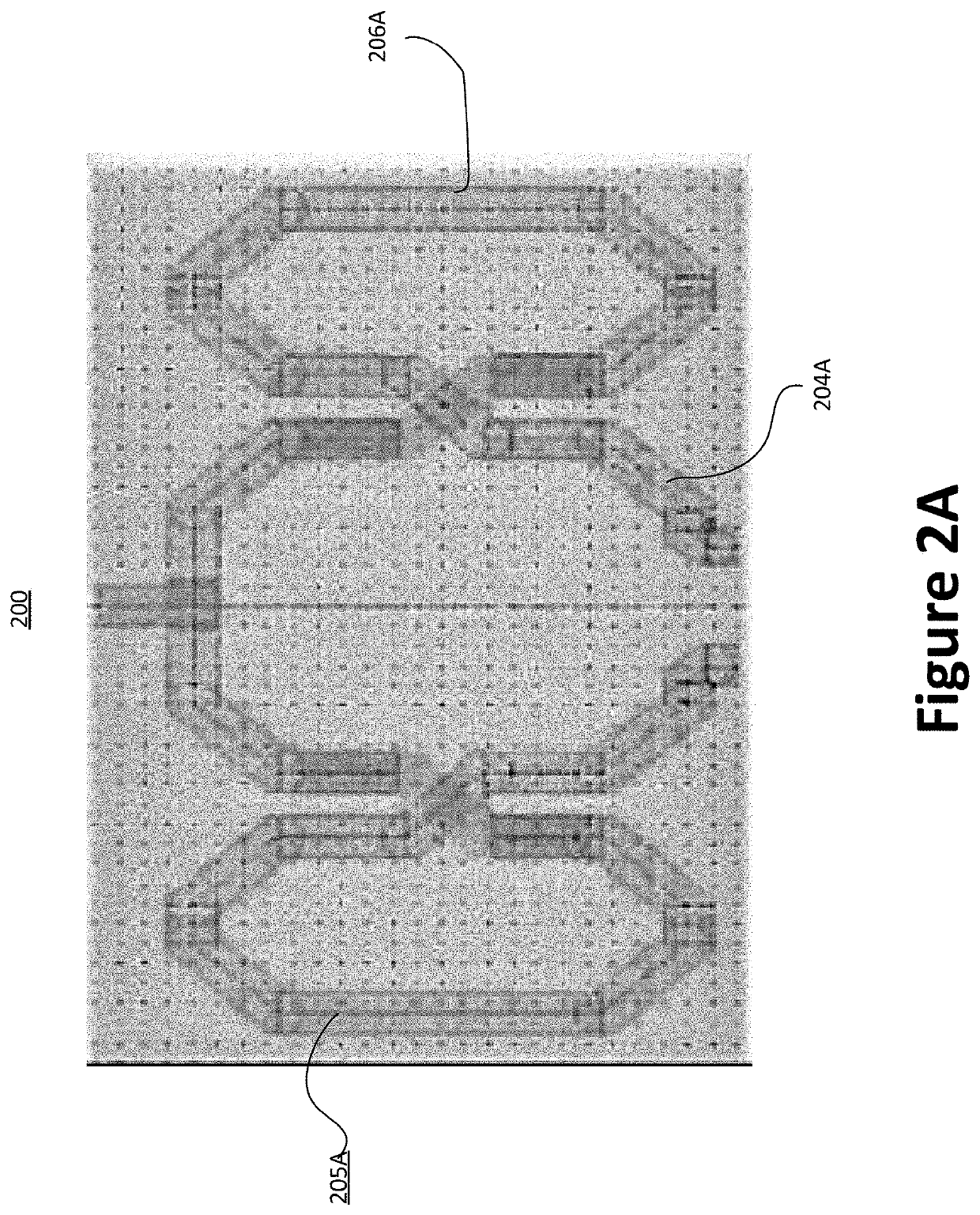
[0027]The present invention is directed to electrical circuits. and more specially, inductor designs that reduce on-chip electromagnetic coupling in a variety of applications. In a specific embodiment, the present invention provides an inductor that includes coils that are configured to generate magnetic fields of opposite polarities. The electromagnetic fields generated by the inductor coils substantially cancel out with each other, thereby minimizing parasitic inductance of the inductor and reducing interference with operations of other components in an integrated circuit. There are other embodiments as well.

[0028]As explained above, existing inductors for VCO circuits are inadequate. An LC-VCO device usually includes inductors configured near one another. The proximity of the inductors deployed at the LC-VCOs may produce undesired electromagnetic field. This undesired electromagnetic field often brings high-clock interference that disrupts the operation of RF transceivers. Moreov...


PUM


Abstract

The present invention is directed to electrical circuits. and more specially, inductor designs that reduce on-chip electromagnetic coupling in certain applications. In a specific embodiment, the present invention provides an inductor that includes coils that are configured to generate magnetic fields of opposite polarities. The electromagnetic fields generated by the inductor coils substantially cancel out with each other, thereby minimizing parasitic inductance of the inductor and reducing interference with operations of other components in an integrated circuit. There are other embodiments as well.

Description

CROSS-REFERENCES TO RELATED APPLICATIONS[0001]NOT APPLICABLESTATEMENT AS TO RIGHTS TO INVENTIONS MADE UNDER FEDERALLY SPONSORED RESEARCH AND DEVELOPMENT[0002]NOT APPLICABLEREFERENCE TO A “SEQUENCE LISTING,” A TABLE, OR A COMPUTER PROGRAM LISTING APPENDIX SUBMITTED ON A COMPACT DISK[0003]NOT APPLICABLEBACKGROUND OF THE INVENTION[0004]The present invention is directed to electrical circuits.[0005]Inductors, as basic components of electrical devices, have a wide of applications. Depending on the applications, inductors can be implemented in different ways to satisfy the desired performance requirement. For example, when inductors are used as certain components of RF receivers, there are certain desired characteristics for these inductors (such as inductance and electromagnetic field). Radio frequency (RF) transceivers can be implemented on a single semiconductor die or chip. Integrating a complete RF transceiver on a single chip presents a number of challenges. RF transceivers are typi...

Claims


Application Information

Patent Timeline
IPC IPC(8): H04B1/38H04L5/16H01F17/00H03B5/12H04B1/40
CPCH03B5/12H01F17/0013H04B1/40H01F2017/002H01F2017/0073H01F2017/008H03B5/1212H03B5/1265H03B5/1243
Inventor GARAMPAZZI, MARCOPISATI, MATTEO
Owner MARVELL ASIA PTE LTD
Learn More