
Dialysis machine and ultrafiltration

a technology of dialysis machine and ultrafiltration, which is applied in the field of dialysis machine, can solve the problems of complicated manufacture, maintenance, miniaturisation and operation of dialysis machin

Active Publication Date: 2021-01-05
QUANTA DIALYSIS TECH LTD
View PDF35 Cites 3 Cited by
  • Summary
  • Abstract
  • Description
  • Claims
  • Application Information

AI Technical Summary

Benefits of technology

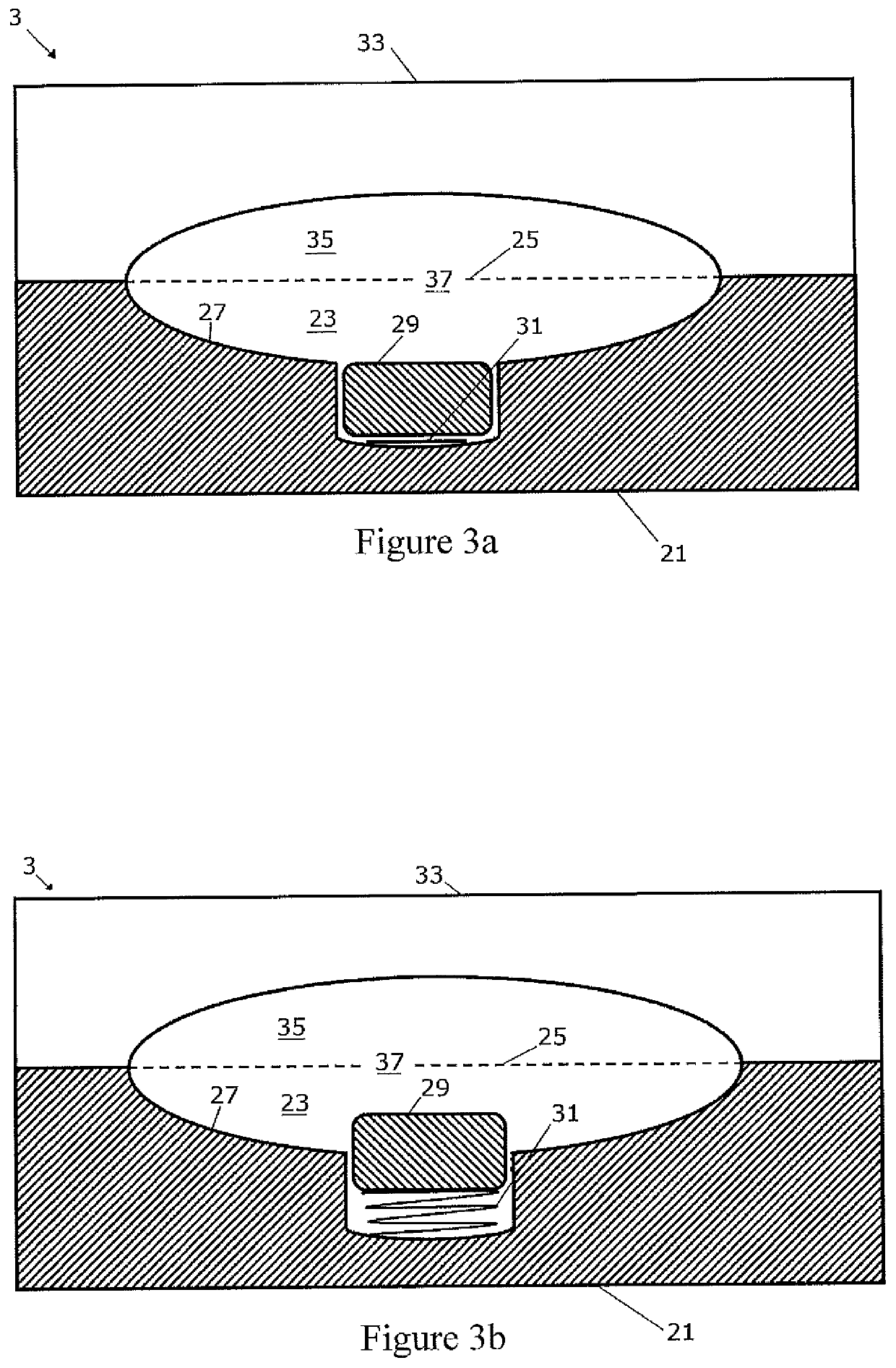
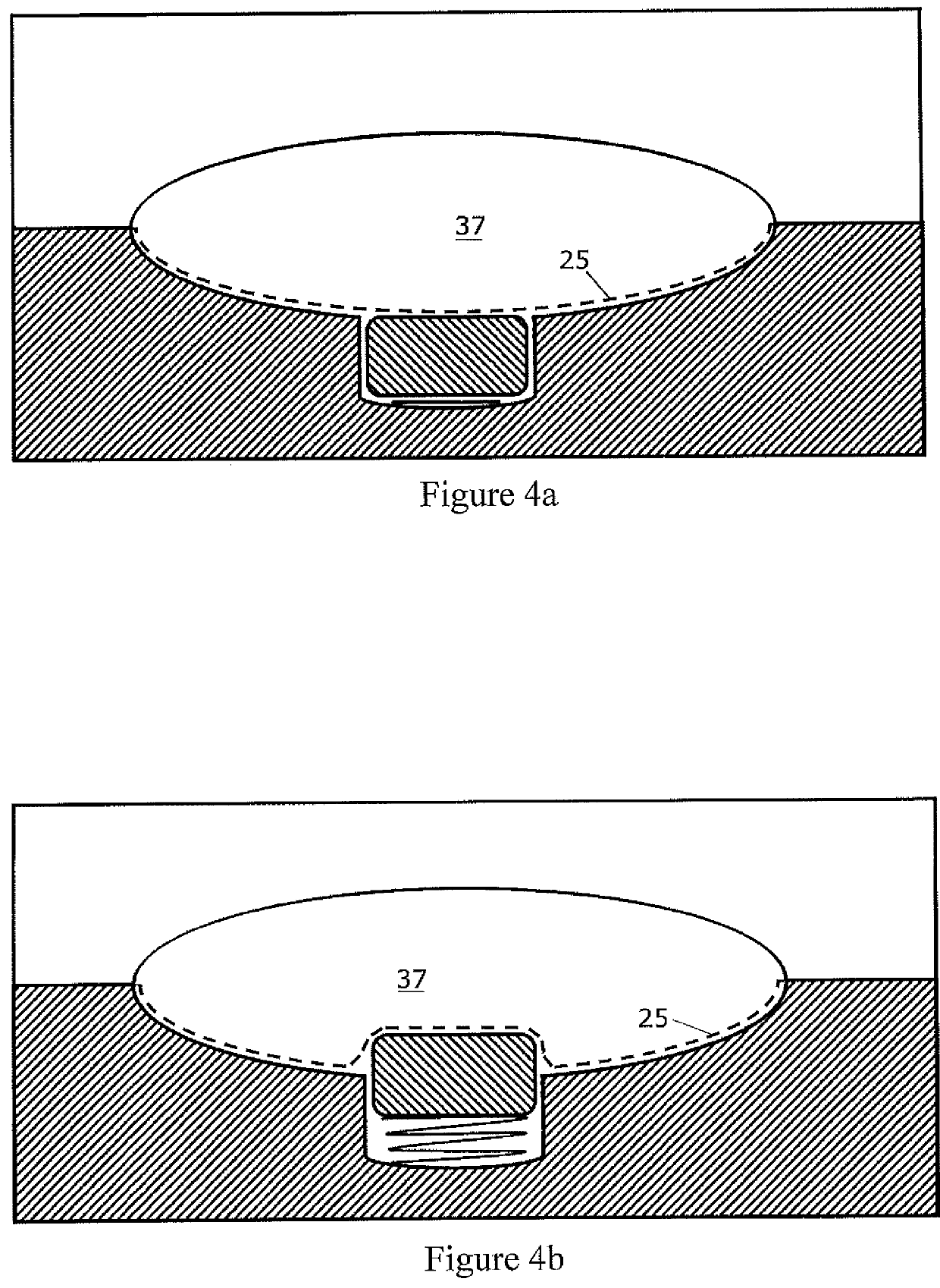
The present invention provides a method for ultrafiltration using two pump systems with different volume flow rates and alternated operation to achieve gradual delivery and removal of excess fluid from the dialyzer. The method involves varying the volume of the pump chambers to change the volume flow rate of at least one pump. This is achieved by actuating the deployable protrusions present in the base of the pump cavity to change the volume of the pump chamber. The technical effect of this invention is improved efficiency in ultrafiltration during dialysis

Problems solved by technology

During most dialysis treatments, it is often the case that excess fluid will be generated by the patient and will interfere with the volumetrically controlled quantities of dialysate passing through the dialyser of the dialysis machine.
However, the presence of a specific pump for ultrafiltration and accompanying tubing, in addition to the dialysate and blood pumps already required by the dialysis machine, complicates the manufacture, maintenance, miniaturisation and operation of dialysis machines.

Method used


Image

  • Dialysis machine and ultrafiltration
  • Dialysis machine and ultrafiltration
  • Dialysis machine and ultrafiltration

Examples


Embodiment Construction

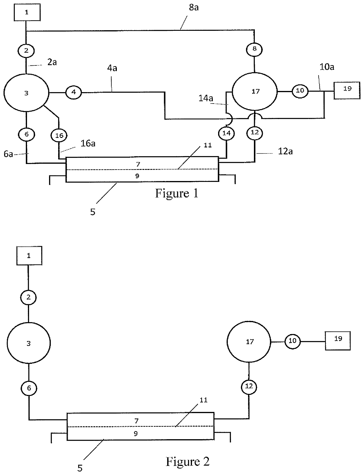
[0048]FIG. 1 shows a typical pumping system for a dialysis machine according to the first aspect of the invention. The system comprises a first pump 3 adapted to receive a fresh dialysate solution from a dialysate source via a first source valve 2 connected via dialysate source line 2a to a source of dialysate 1. The dialysate source line 2a has a first dialysate source valve 2 to control flow of dialysate from the source 1 to the first pump 3. First pump 3 has fluid connections to a dialysate inlet line 6a, dialysate drain line 4a and dialysate outlet line 16a. Dialysate inlet line 6a has dialysate inlet valve 6 thereon. Dialysate drain line 4c has dialysate drain valve 4 thereon. Dialysate outlet line 16a has dialysate outlet valve 16 thereon.

[0049]Dialysate inlet line 6a and dialysate outlet line 16a are connected, in fluid communication, to the dialysate side of a dialyser 5 in known manner. Dialysate drain line 4a is connected in fluid communication with a dialysate drain 19. I...


PUM


Abstract

The invention relates to a dialysis machine capable of performing ultrafiltration without the need for a dedicated ultrafiltration pump. The system uses a pair of membrane flow balance pumps wherein the operation and / or the volume flow rate of the pumps can be modified during operation to bring about a net movement of dialysate either into or from the dialyser. The direction of flow of the dialysate in the dialyzer is reversible and the dialyzer can comprise two dialysate inlets, one at each end, and two dialysate outlets, one at each end.

Description

[0001]This application is a National Stage Entry entitled to and hereby claiming priority under 35 U.S.C. §§ 365 and 371 to corresponding PCT Application No. PCT / GB2016 / 053339, filed Oct. 27, 2016, entitled “Dialysis Machine And Ultrafiltration”, which in turn claims priority to G.B. Patent Application No.: 1519084.6, filed Oct. 28, 2015, entitled the same. The disclosures of the above applications are incorporated herein by reference in their entireties.FIELD OF INVENTION[0002]The invention relates to a dialysis machine suitable for performing ultrafiltration. In particular, the invention relates to a dialysis machine where ultrafiltration can be carried out without the need for a specific ultrafiltration pump.BACKGROUND OF INVENTION[0003]Dialysis is a treatment which replaces the renal function of removing excess fluid and waste products (e.g. potassium) from the blood. The treatment is either employed where renal function has deteriorated to an extent that uremic syndrome becomes...

Claims


Application Information

Patent Timeline
Patent Type & Authority Patents(United States)
IPC IPC(8): A61M1/16A61M1/26A61M1/34
CPCA61M1/1647A61M1/16A61M1/1637A61M1/1649A61M1/267A61M1/341A61M2205/12A61M2205/128A61M1/155A61M1/1565A61M1/1562A61M1/1561A61M1/1601
Inventor WALLACE, MARK
Owner QUANTA DIALYSIS TECH LTD
Learn More