Linear vibration motor

a linear vibration and motor technology, applied in the field of miniature motors, can solve the problems of difficult to ensure the vibration balance of the vibrator, polarized vibration is easily caused, and the performance of the linear vibration motor is affected, so as to achieve the effect of improving the uniformity of the force receiving the vibrator, improving the stability and balance of the vibration of the vibrator, and improving the stability of the vibration

Active Publication Date: 2021-01-05
GOERTEK INC
View PDF18 Cites 16 Cited by
  • Summary
  • Abstract
  • Description
  • Claims
  • Application Information

AI Technical Summary

Benefits of technology

[0005]Regarding the above defects, the technical problem to be solved by the present invention is to provide a linear vibration motor which has a simple structure, is low in assembly difficulty, does not generate polarized vibration, and is better in low frequency performance and high in overall performance.

Problems solved by technology

Since the vibrator has certain dimensions in length, width and height and also has a certain weight, the structure of the existing elastic support and a connection mode thereof to the vibrator and the housing make it difficult to ensure the vibration balance of the vibrator.
As a result, the polarized vibration is easily caused and the performance of the linear vibration motor is affected.
Although this method solves the technical problem of polarized vibration of the vibrator, the motor becomes more complex in structure and is higher in assembly difficulty.
It is difficult to implement this method with continuous decrease of the motor volume.
In addition, the addition of the positioning shaft also reduces the volume and weight of a mass block.
Consequently, the resonant frequency of the motor is increased, the low frequency performance of the motor is reduced, and thus the improvement on the overall performance of the motor is seriously affected.

Method used


Image

  • Linear vibration motor
  • Linear vibration motor
  • Linear vibration motor

Examples


embodiment one

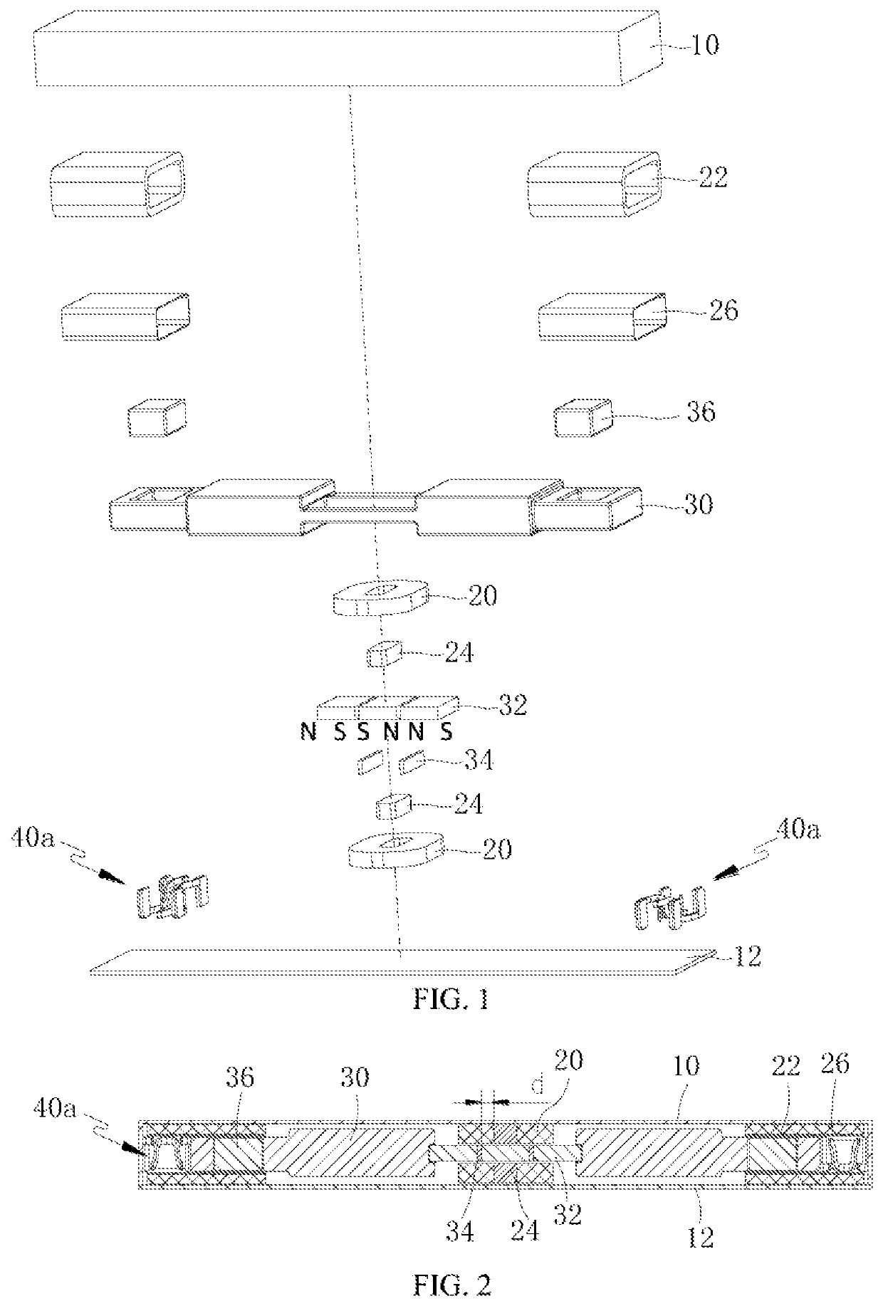
[0037]As shown in FIGS. 1-4, a linear vibration motor is of a cuboid structure and comprises a housing, a stator, a vibrator and at least two sets of elastic support assemblies 40a which are located at two ends of the vibrator, respectively, and used for supporting the vibrator and providing elastic restoring forces. Each set of the elastic support assemblies 40a comprises at least two elastic supports 42. The elastic supports 42 are elastic sheets or springs. The housing comprises an upper housing 10 and a lower housing 12 which are coupled together. The upper housing 10 is of a box-shaped structure with one open end. The lower housing 12 is of a plate-like structure. The open end of the upper housing 10 is buckled on the lower housing 12. The stator is fixed on the upper housing 10 and the lower housing 12. The vibrator is suspended, through the elastic support assemblies 40a, in a space defined by the upper housing 10 and the lower housing 12.

[0038]As shown in FIGS. 1-3, the vibr...

embodiment two

[0046]This embodiment is basically the same as Embodiment One, except the followings.

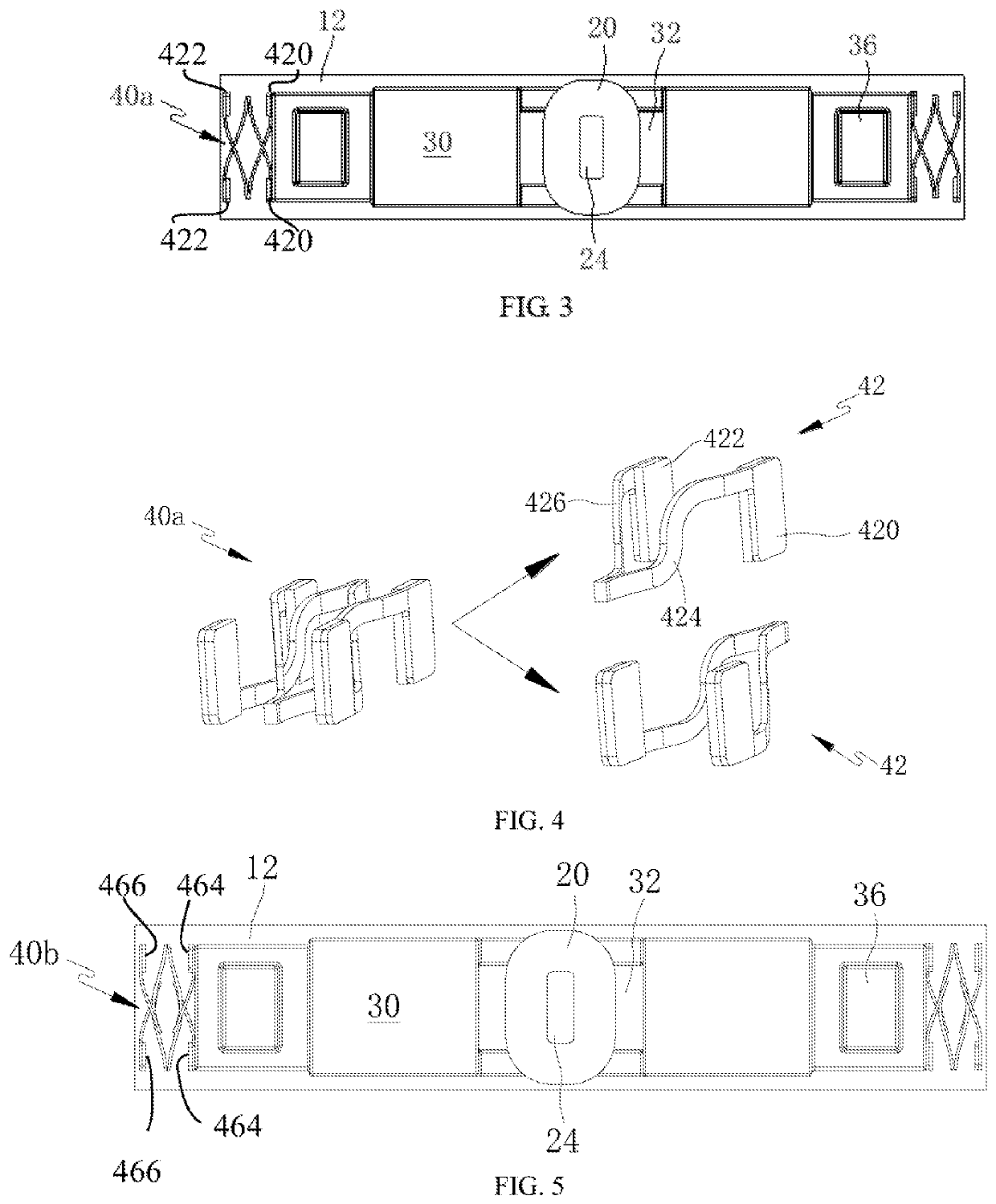
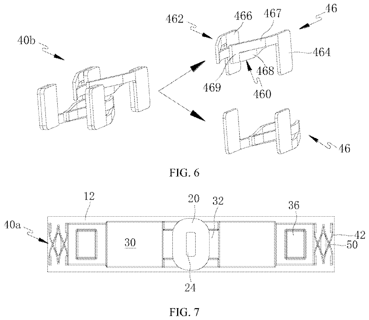
[0047]As shown in FIGS. 5 and 6, an elastic support assembly 40b comprises two elastic supports 46 having the same structure. The two elastic supports 46 are likewise arranged symmetrically vertically and in the front-rear direction. A first connection point 464 and a second connection point 466 on the same elastic support 46 are located on the same side of a central axis of the vibrator. The first connection point 464 is coupled at an end of the mass block 30. The second connection point 466 is coupled to a side wall, perpendicular to the vibration direction of the vibrator, of the upper housing 10 (see FIG. 1). The height of the elastic support assembly 40b is identical with the height of the end of the mass block 30, and the height of both the first connection points 464 and the second connection points 466 is identical with the height of the end of the mass block 30. Moreover, the width (i.e., a...

embodiment three

[0050]This embodiment is basically the same as Embodiment Two, except that the followings.

[0051]As shown in FIG. 7, a damping element 50 is arranged in a space defined by two elastic supports 42 in the same set of elastic support assemblies 40a. The damping element 50 may be made of, but not limited to sponge, silica gel, rubber, foam or the like, and may be made of any material as long as it has a damping effect. The damping element 50 may provide certain assistance during a restoring process of the elastic support 42, shorten the vibration return time of the vibrator and realize rapid reciprocating movement of the vibrator. Thus, the performance of the motor is further improved. Moreover, the vibrator is effectively prevented from collision with the housing. Thus, for the motor, the stability is improved and the service life is prolonged.

[0052]As shown in FIG. 7, the damping element 50 may not only be arranged on the inner side of the elastic support assembly 40a as shown in the f...


PUM


Abstract

A linear vibration motor comprising a housing, a stator, an vibrator, and two sets of elastic support assemblies which are located at two ends of the vibrator, respectively, and used for supporting the vibrator and providing elastic restoring forces, wherein each set of the elastic support assemblies comprises at least two elastic supports. Each elastic support comprises a first connection point coupled to the vibrator and a second connecting point coupled to the housing. both the first connection point and the second connection point which are located on the same elastic support are located on the same side of a central axis of the vibrator, and the central axis is parallel to a vibration direction of the vibrator; and the second connection point is coupled onto a side wall, perpendicular to the vibration direction of the vibrator, of the housing. The linear vibration motor of the present invention has a simple structure, is low in assembly difficulty and high in production efficiency.

Description

CROSS-REFERENCE TO RELATED APPLICATIONS[0001]This application is a National Stage of International Application No. PCT / CN2016 / 084791, filed on Jun. 3, 2016, which claims priority to Chinese Patent Application No. 201510835647.0, filed on Nov. 25, 2015, both of which are hereby incorporated by reference in their entireties.BACKGROUNDTechnical Field[0002]The present invention relates to the technical field of miniature motors, and in particular, to a linear vibration motor.Description of Related Art[0003]As one type of motors, a linear vibration motor with a horizontal vibration direction is mostly used in portable electronic products such as a mobile phone, a handheld game machine and a handheld multimedia entertainment device. The linear vibration motor usually comprises a housing, a stator and a vibrator. The stator comprises coils and magnetic conduction cores which are fixed on the housing. The vibrator comprises permanent magnets corresponding to the coils and the magnetic condu...

Claims


Application Information

Patent Timeline
Patent Type & Authority Patents(United States)
IPC IPC(8): H02K33/02H02K33/16H02K33/14
CPCH02K33/02H02K33/14H02K33/16
Inventor LIU, CHUNFAZU, FENGLEI
Owner GOERTEK INC
Why Eureka
Try Eureka