Braking force control apparatus for vehicle

a technology of braking force control and vehicle, which is applied in the direction of braking systems, braking components, transportation and packaging, etc., can solve the problems of unnatural fluctuation of the pitch attitude of the vehicle, inability to limit the change gradient of regenerative braking force, and inability to effectively improve fuel economy

Active Publication Date: 2021-01-12
TOYOTA JIDOSHA KK
View PDF17 Cites 0 Cited by
  • Summary
  • Abstract
  • Description
  • Claims
  • Application Information

AI Technical Summary

Benefits of technology

[0013]Therefore, the target pitch gain when the target braking force of the vehicle changes in a range larger than the maximum regenerative braking force can be changed little by little and smoothly. Accordingly, it is possible to prevent the gain from abruptly changing and to reduce the possibility that a pitch attitude of the vehicle unnaturally fluctuates when a braking situation changes from the situation where only the regenerative braking forces are generated to the situation where the friction braking forces are also generated, and also when the regenerative braking forces and the friction braking forces change in the reverse manner.
[0016]According to the above aspect, by using the function having a difference between the target braking force of the vehicle and a total of the regenerative braking forces as a variable, a target pitch gain can be calculated so that a pitch gain of the vehicle when the target braking force of the vehicle increases beyond the maximum regenerative braking force gradually approaches a desired pitch gain. Therefore, as the target braking force of the vehicle increases in a range equal to or more than the maximum regenerative braking force, the target pitch gain gradually changes so as to approach the desired pitch gain. Accordingly, when the braking situation changes from the situation where only the regenerative braking forces are generated to the situation where the friction braking forces are also generated, the pitch attitude of the vehicle can be changed little by little and smoothly so as to gradually approach a desired pitch attitude, so that it is possible to effectively reduce the possibility that the pitch attitude of the vehicle unnaturally fluctuates.
[0017]It is to be noted that as long as a target pitch gain can be calculated so that a pitch gain of the vehicle when the target braking force of the vehicle exceeds the maximum regenerative braking force and increases in the range equal to or more than the maximum regenerative braking force gradually approaches the desired pitch gain, the function may be an arbitrary function. In particular, as will be described in detail later, the function is preferably a function like a quadratic function so that a rate of change of the target pitch gain according to a change of the target braking force of the vehicle can be reduced as a difference between the target braking force of the vehicle and the total of the regenerative braking forces increases. When the function is a function such as a quadratic function, it is possible to effectively reduce the possibility that the pitch attitude of the vehicle unnaturally fluctuates as compared to where the target pitch gain is calculated by a linear function having as a variable a difference between the target braking force and a total of the regenerative braking forces of the vehicle.
[0021]According to the above aspect, when the target braking force of the vehicle is larger than the preset specified braking force, the target pitch gain is the desired pitch gain. Therefore, the pitch attitude of the vehicle can be kept constant even when the target braking force of the vehicle changes in a range larger than the preset predetermined braking force. Accordingly, unnatural fluctuation of the pitch attitude of the vehicle can be prevented, and the pitch angle of the vehicle can be prevented from becoming excessive.
[0023]According to the above aspect, the target pitch gain can be calculated as a sum of a pitch gain of the vehicle when the target braking force of the vehicle is equal to or less than the maximum regenerative braking force and a pitch gain correction amount proportional to a difference between the target braking force of the vehicle and a total of the regenerative braking forces. Therefore, when the target braking force of the vehicle is larger than the maximum regenerative braking force, the target pitch gain can be changed linearly according to a difference between the target braking force of the vehicle and the total of the regenerative braking forces. Accordingly, a ratio of the regenerative braking force and the friction braking force can be prevented from changing stepwise when the braking situation changes from the situation where only the regenerative braking forces are generated to the situation where the friction braking forces are generated, and also when the regenerative braking forces and the friction braking forces change in the reverse manner.
[0028]Therefore, by controlling the front-rear wheel distribution ratio of the friction braking force without changing the regenerative braking force and the front-rear wheel distribution ratio of the regenerative braking force, it is possible to control the pitch angle of the vehicle to the target pitch angle while controlling the braking force of the vehicle to the target braking force.

Problems solved by technology

Therefore, in a situation where the regenerative braking force and the friction braking force change as described above, it is not possible to limit a change gradient of the regenerative braking force as by the braking force control device described in the above-mentioned Japanese Patent Application Laid-open Publication.
Therefore, in a situation where the regenerative braking force and the friction braking force change as described above, it is inevitable that a pitch attitude of the vehicle unnaturally fluctuates due to an abrupt change in the ratio of the regenerative braking force and the friction braking force.
It is to be noted that in a situation where the regenerative braking force and the friction braking force change as described above, if it is attempted to moderate the change in the ratio of the regenerative braking force and the friction braking force, it is forced to sacrifice regenerative braking and it becomes impossible to effectively improve fuel economy.

Method used


Image

  • Braking force control apparatus for vehicle
  • Braking force control apparatus for vehicle
  • Braking force control apparatus for vehicle

Examples


embodiments

[0085]Next, some embodiments of the present disclosure will be described in detail.

first embodiment

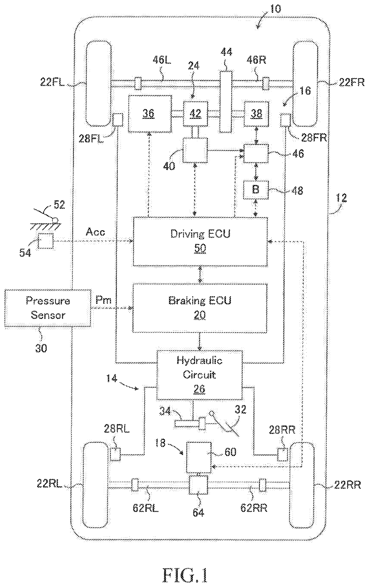
[0086]As shown in FIG. 1, the braking force control apparatus 10 according to the first embodiment is adapted to a vehicle 12 with a hybrid system. The braking force control apparatus 10 includes a friction braking device 14, a front wheel regenerative braking device 16, a rear wheel regenerative braking device 18, a braking electronic control unit (ECU) 20 as a control device for controlling the friction braking device and the regenerative braking devices. The friction braking device 14 applies friction braking forces to left and right front wheels 22FL, 22FR and left and right rear wheels 22RL, 22RR. The front wheel regenerative braking device 16 is a part of the hybrid system 24 and applies a regenerative braking forces to the left and right front wheels 22FL and 22FR. The rear wheel regenerative braking device 18 applies regenerative braking forces to the left and right rear wheels 22RL and 22RR.

[0087]Although not shown in the drawing, the vehicle 12 has a center of gravity betw...

second embodiment

[0121]FIG. 9 is a schematic configuration diagram showing a second embodiment of the vehicle braking force control device according to the present invention having a front wheel regenerative braking device. In FIG. 9, the same members as those shown in FIG. 1 are assigned to the same reference numerals as those shown in FIG. 1. This also applies to the later-described third embodiment.

[0122]In the second embodiment, the rear wheel regenerative braking device 18 in the first embodiment is not provided. Therefore, no regenerative braking force is applied to the left and right rear wheels 22RL and 22RR, and the regenerative braking forces are applied only to the left and right front wheels 22FL and 22FR by the front wheel regenerative braking device 16. The other points of this embodiment are the same as those of the first embodiment.

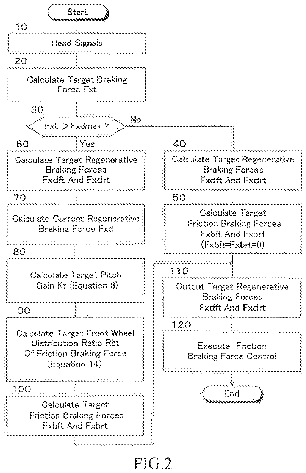
[0123]In the second embodiment, the braking force control is executed according to the braking force control program corresponding to the flowchart shown ...


PUM


Abstract

A braking force control apparatus for a vehicle has a friction braking device, a regenerative braking device, and a control unit for controlling the friction braking device and the regenerative braking device. The control unit is configured to calculate a target pitch gain of the vehicle so that a pitch gain of the vehicle gradually changes in accordance with a difference between a target braking force of the vehicle and a regenerative braking force when the target braking force of the vehicle exceeds a maximum regenerative braking force and changes within a range larger than the maximum regenerative braking force, and to control a front-rear wheel distribution ratio of a friction braking force so that the pitch gain of the vehicle becomes the target pitch gain and the friction braking force becomes the difference between the target braking force of the vehicle and the maximum regenerative braking force.

Description

CROSS-REFERENCE TO RELATED APPLICATION[0001]The disclosure of Japanese Patent Application NO. JP2017-195165 filed on Oct. 5, 2017 is incorporated by reference in its entirety.BACKGROUND1. Technical Field[0002]The present disclosure relates to a braking force control apparatus for a vehicle such as an automobile, and more particularly to a braking force control apparatus for controlling a friction braking force and a regenerative braking force.2. Description of the Related Art[0003]It is well known to provide a vehicle such as an automobile with a regenerative braking device in addition to a friction braking device and to preferentially generate a regenerative braking force rather than a friction braking force when braking the vehicle in order to improve fuel economy. In particular, in a vehicle provided with a regenerative braking device only on one of the front wheels and the rear wheels, when a ratio of a regenerative braking force and a friction braking force changes, a front-rea...

Claims


Application Information

Patent Timeline
Patent Type & Authority Patents(United States)
IPC IPC(8): B60L7/26B60W30/18B60T8/171B60T8/172B60T8/1755B60W10/08B60W10/188
CPCB60L7/26B60T8/171B60T8/172B60T8/17555B60W30/18127B60T2270/604B60W10/08B60W10/188B60L7/10B60T8/17B60L7/18Y02T10/72
Inventor YOSHIDA, KAZUAKI
Owner TOYOTA JIDOSHA KK
Why Eureka
Try Eureka