Device and method for generating gas bubbles in a liquid

a gas bubble and liquid technology, applied in the direction of mixing methods, rotary stirring mixers, mixers, etc., can solve the problems of increasing the cost of gas bubble production, requiring a relatively large amount of energy, and the method is not efficient or efficient, so as to achieve uniform bubble production

Active Publication Date: 2021-01-26
AKVOLA TECH GMBH
View PDF45 Cites 1 Cited by
  • Summary
  • Abstract
  • Description
  • Claims
  • Application Information

AI Technical Summary

Benefits of technology

[0017]In the present invention, a device for generating gas bubbles in a liquid, more particularly microbubbles, is provided which allows bubble production by means of suitable gassing discs. For this purpose, the compressed gas is introduced into the horizontally mounted rotatable hollow shaft (composed of a smaller inner and a larger outer hollow shaft) and fed via the gassing discs, which are composed for example of a ceramic membrane with a gas channel, into the liquid. The use of two hollow shafts lying inside one another allows uniform and symmetrical distribution of pressure inside the larger hollow shaft. The discs are thus symmetrically supplied with gas, and uniform bubble production in the medium to be gassed is achieved.
[0018]As explained below, the ceramic membrane has a pore size, for example, of 2 μm, which results in the formation of bubbles with a bubble size of between 40 and 60 μm. Because of the rotation of the hollow shaft and the ceramic discs mounted on the hollow shaft, shear forces act on the air bubbles coming out of the ceramic discs that affect the size of the gas bubbles and the gas foam. The strength or magnitude of the acting shear forces thus directly affect the efficiency of bubble formation. The strength of the shear forces per se is in turn affected by the rotation speed of the hollow shaft, wherein the rotation speed of the hollow shaft can be up to 250 rpm. The dirt particles contained in the liquid (such as organic substances or biological substances) then attach themselves to the bubbles formed in the liquid in the form of a foam and rise in the form of a corresponding gas-bubble agglomerate to the surface of the liquid. The solid layer formed on the surface of the liquid as a result can then be mechanically separated. The specific combination of gas oscillation, direct gas injection in the feed line and hollow shaft, and the vertical arrangement of the gassing discs on the horizontal hollow shaft make it possible to produce minute bubbles in an energetically favorable and thus economical manner, which makes large-scale application of the device appropriate.

Problems solved by technology

The DAF method allows highly favorable separation of microalgae and other minute organisms, oils, colloids, and other organic and inorganic particles from high-load wastewater, but requires a relatively large amount of energy because of the introduction of air into the liquid using a saturation column, which entails high energy consumption.
At high temperatures (greater than 30° C.) and salt contents (greater than 30,000 ppm), the method works less and less efficiently or not at all.
However, such small pore sizes are by no means practical, for example in the use of salt water or highly polluted water such as water containing sludge, as water containing salt or sludge has a higher density or viscosity than normal water and clogs the small pores of the ceramic discs.
The smaller the pore size, the more difficult it is to produce bubbles on immersed porous surfaces and thus the greater the energy required for this purpose.
The membrane and device described in WO 2008 / 013349 A1 are therefore by no means economically suitable for large-scale industrial use.
However, the production of minute bubbles (less than 100 μm) for large-scale industrial use is not possible with the device described in EP 2081666 B1.

Method used


Image

  • Device and method for generating gas bubbles in a liquid
  • Device and method for generating gas bubbles in a liquid
  • Device and method for generating gas bubbles in a liquid

Examples


Embodiment Construction

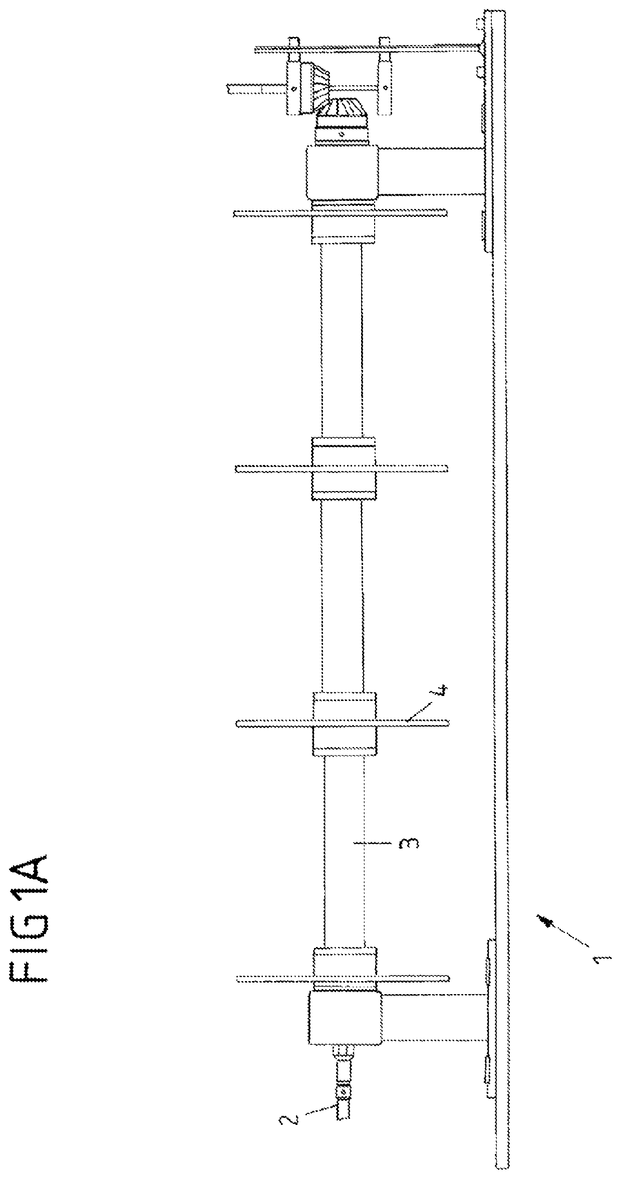
"d_n">[0064]The general structure of a first embodiment of the device according to the invention for producing gas bubbles is shown in FIG. 1A.

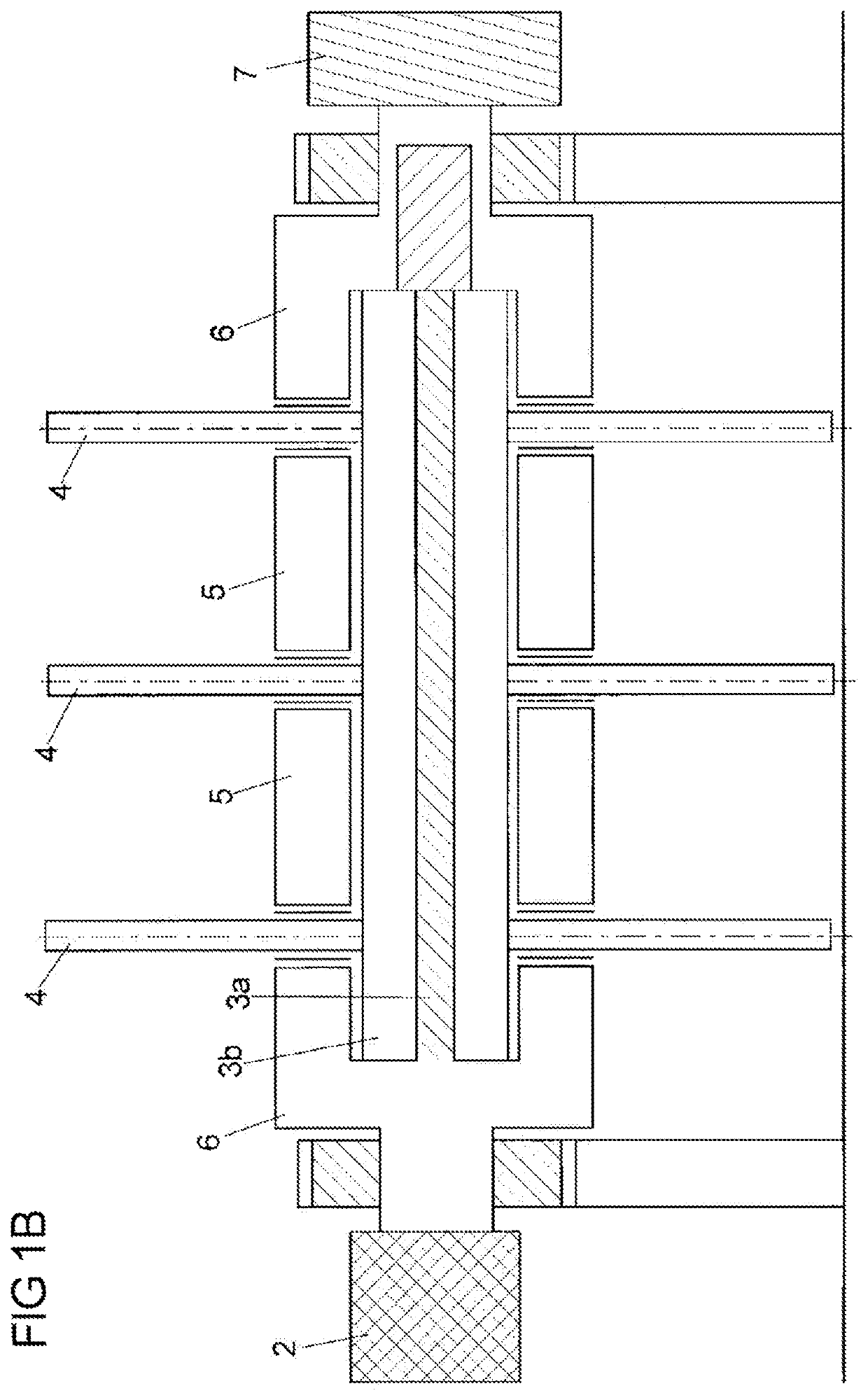
[0065]The side view of FIG. 1A shows a device 1 with a feed line 2 for feeding the compressed gas and a hollow shaft 3 through which the compressed gas is further introduced into the gassing discs 4.

[0066]In the embodiment shown in FIG. 1A, four circular gassing discs of a ceramic material are arranged on the hollow shaft. The ceramic discs are composed of aluminum oxide and have an outer diameter of 152 mm and an inner diameter of 25.5 mm. The membrane surface area is 0.036 m2, and the pore size of the gassing discs is in the range of 2 μm. The gas is introduced from the hollow shaft 3 into a hollow cavity of the ceramic disc 4 and penetrates from the inside of the hollow cavity through the pores of the ceramic material into the liquid to be purified, which is provided around and above the hollow shaft having the gassing discs, forming micro...


PUM

PropertyMeasurementUnit
pore sizeaaaaaaaaaa
pore sizeaaaaaaaaaa
pressureaaaaaaaaaa

Abstract

The invention relates to a device for generating gas bubbles in a liquid in a container, including at least one rotatable hollow shaft arranged horizontally in at least one container; at least one gassing disc arranged vertically on the at least one hollow shaft; and at least one feed line for supplying at least one compressed gas to the interior of the at least one hollow shaft, said compressed gas being brought into the feed line and hollow shaft directly, without a liquid carrier.

Description

CROSS-REFERENCE TO RELATED APPLICATIONS[0001]This application is the United States national phase of International Application No. PCT / EP2016 / 060504 filed May 11, 2016, and claims priority to German Patent Application No. 102015208694.1 filed May 11, 2015, the disclosures of which are hereby incorporated in their entirety by reference.BACKGROUND OF THE INVENTIONField of the Invention[0002]The present invention relates to a device for generating gas bubbles in a liquid, a method for generating gas bubbles in a liquid using a device, a system for water purification comprising a device, and a method for water purification using a system.Description of Related Art[0003]Gas bubbles in liquids are necessary for a variety of different applications, such as, for example, in order to dissolve gas in the liquid. An area of application of gas bubbles in liquids that is becoming increasingly interesting and important is the purification of water and other liquids by the so-called flotation meth...

Claims


Application Information

Patent Timeline
Patent Type & Authority Patents(United States)
IPC IPC(8): B01F3/04B01F7/10B01F27/73
CPCB01F3/04588B01F7/10B01F7/105B01F2003/04546B01F2003/04567B01F23/2332B01F23/23311B01F23/23314B01F27/731B01F27/73
Inventor BEERY, MATANTYCHEK, GREGORLUDWIG, JOHANNA
Owner AKVOLA TECH GMBH
Why Eureka
Try Eureka