
Portable robotic construction system

a robotic construction and portable technology, applied in mechanical machines/dredgers, masonry, land surveying, etc., can solve the problems of large scale additive fabrication prototypes in development, time-consuming and labor-intensive tasks, and the inability to move large structures into place at a construction site. light weight and low torque tasks

Active Publication Date: 2021-02-16
PEARSON JR KENT DOUGLAS
View PDF22 Cites 22 Cited by
  • Summary
  • Abstract
  • Description
  • Claims
  • Application Information

AI Technical Summary

Benefits of technology

The movable gantry robotic apparatus described in this patent text has several technical effects. First, it has a chassis platform with a propulsion system, power supply, and computing system controller. Second, it has an expandable and rotating turret system that can support a gantry bridge. Third, it has a bridge conveyor belt system with a plurality of conveyor accessory arms that can move various items along the gantry bridge. Fourth, it has multiple sensors and a computing system that determine weight load on the trolley and gantry bridge and send instructions to adjust the gantry bridge to distribute weight load between the extendable gantry support legs. Fifth, it has a trolley system and accessory arms that can hold tools, construction materials, tanks, or concrete mixers. Lastly, it has a hydraulic pistons and risers to help adjust elevation and angle of the gantry bridge.

Problems solved by technology

Moving large structures into place at a construction site is time consuming and a costly procedure often requiring extra lift equipment to assemble the robotic equipment and structures.
Currently, there are only a few large scale additive fabrication prototypes under development which focus primarily on extruding material from a computer controlled nozzle and which can only handle light weight and low torque tasks.
These devices are limited to weight restrictions due to their physical constraints on an extended boom which results in smaller working areas and lighter bricks that can be utilized for pick and place.
The functionality of these booms is limited in capabilities to pick and place of bricks as well as additive concrete techniques.
While these non-linear robotic arms that are attached to booms or at the end of excavators' arms do improve pick and placing procedures and additive fabrication applications, they are not as efficient as linear robotic systems which are the most common moving robotic systems for factory assemblies and rapid prototype equipment.
The disadvantages are that the prefab material needs to be moved fully assembled by truck to the site which is bulky and expensive.
There are, however, a lot of inefficiencies in the current construction method which often causes delays in finishing a project on time and with high quality.
An underperforming team can cause other teams to be delayed or have the teams have to work around issues created by the underperforming team.
They most likely need room at the site to maneuver and often cause more environmental damage than is desired.
These devices often emit fumes and are not environmentally friendly.
Construction sites are often loud, smelly, and the environment is more affected due to the construction equipment footprint and dirt removal capabilities.
Excavators need to pick up the dirt and empty the dirt into the dump truck which may take a lot of time to accomplish.
The main issue is that the conveyor belt needs to be within an arms-reach of the excavator resulting in the conveyor belt being constantly moved.
This can be more of an inconvenience for the excavator operator.
Although outrigger legs on a lift or crane help the lift and crane with heavier objects, the lift and crane is still limited by the physical properties associated with leverage, the fulcrum point, and the weight.

Method used


Image

  • Portable robotic construction system
  • Portable robotic construction system
  • Portable robotic construction system

Examples


Embodiment Construction

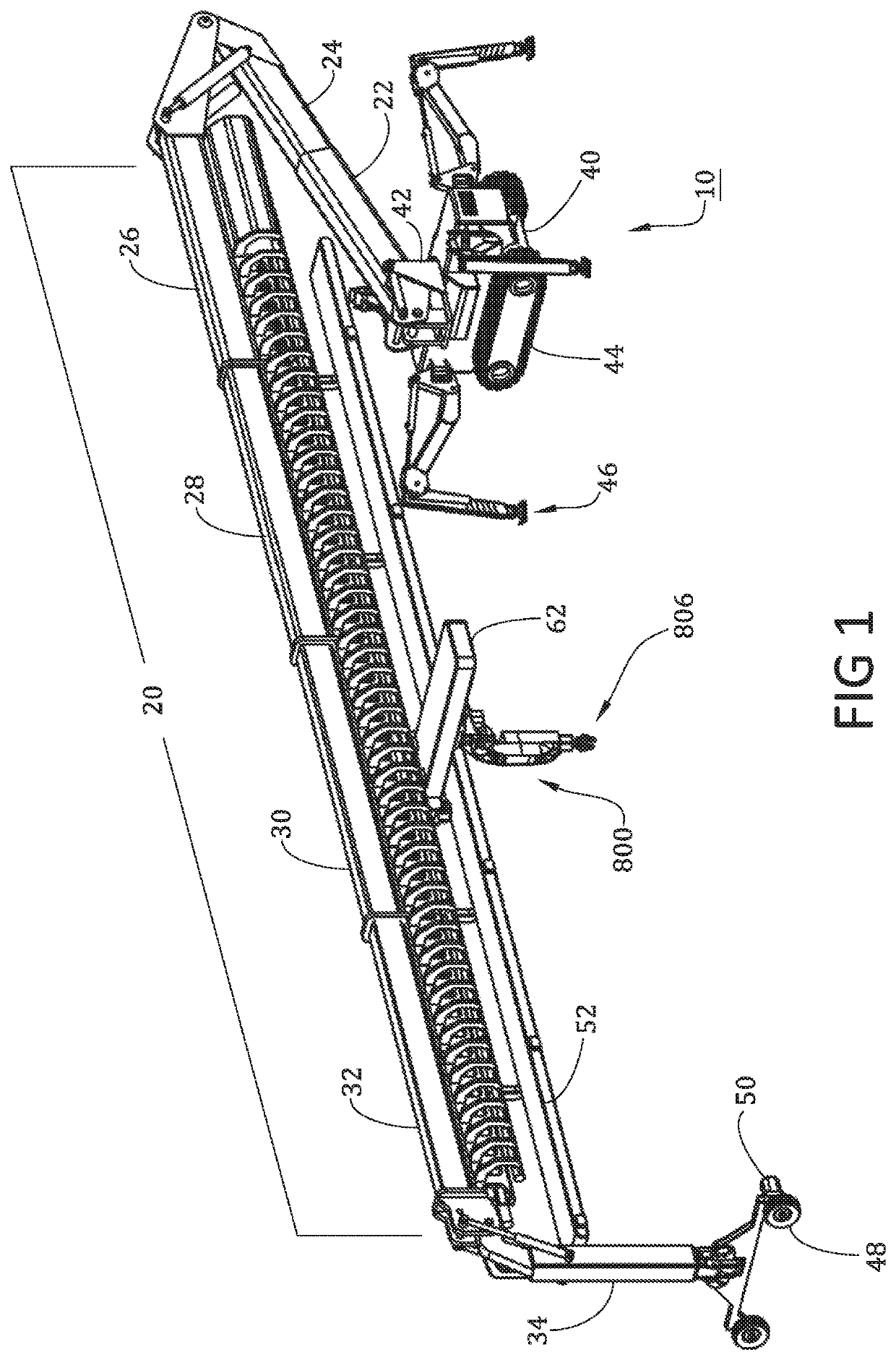
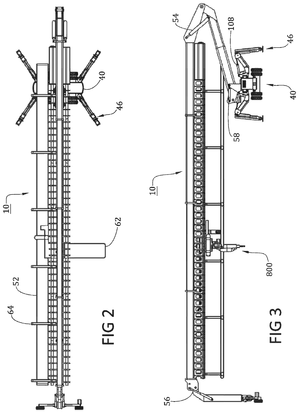
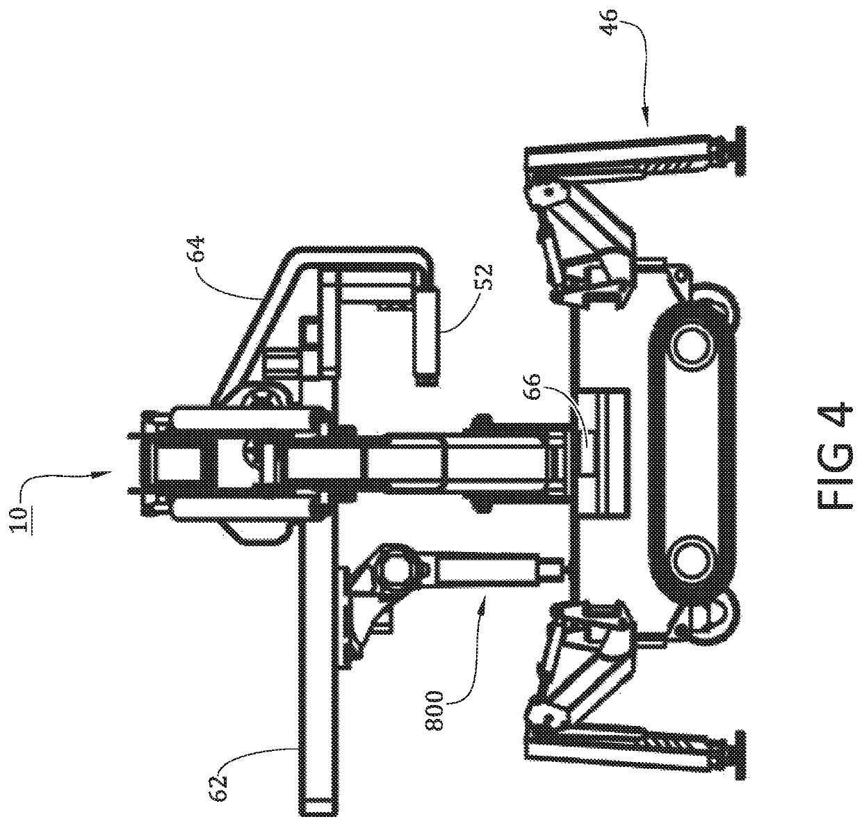
[0229]FIGS. 1,2,3,4 and 5 illustrates the presently preferred embodiment 10 of the invention. The drawings illustrate a portable and expandable gantry with robotic arm attachments and implements 806 to oversee construction and assembly procedures. The bridge of the gantry 20 is made up of extendable bridge boom sections of the gantry 26, 28, 30 and 32. The main chassis 40 is connected to a lower turret boom riser 22 by a turret 42 that can be mechanically controlled to rotate 360 degrees as shown in FIG. 6. The lower turret boom riser 22 can pivot upwards as well as extend outward with the extendable boom 24 to increase the height of one side of the gantry. On the other side of the gantry bridge is a support jib boom leg 34 that can pivot from the extendable bridge boom section of gantry 32 shown in FIGS. 1, 18, 19, and 20. The support boom leg can articulate creating different gantry configurations which can be seen in FIGS. 40, 41, and 42. The support leg has Extendable Support Ji...


PUM


Abstract

A robotic system having a movable gantry robot (10) for conducting construction operations. The gantry may have an expandable bridge (20) and articulated gantry support legs (34) as well as a support track system (60) holding a gantry robot (800) which may hold one or more implements and peripheral devices (806). The device can be moved by propulsion mechanisms, a controller, and one or more geo-positioned control devices to provide position information for the robotic gantry as it moves back and forth along a plurality of work sites (700). The robotic gantry is connected to a power supply system (236). The controller is automated, self-navigating, and activates, deactivates, and / or changes the operation of the propulsion mechanisms, and deploys, retracts, activates, deactivates, and / or changes the operation of one or more of the construction implements. The height of the frame may be adjusted by extending and rotating risers and booms to accommodate different building heights or sub-level heights at a worksite. A conveyor system is optimized for removing dirt from or delivering material to the robotic arm. This invention can be applied to automating construction jobs including surveying, land preparation, excavation, foundation, masonry, framing, and additive fabrication.

Description

[0001]This application claims the benefit of U.S. Provisional Patent Appl. No. 62 / 524,140, filed on Jun. 23, 2017, which is incorporated by reference in entirety.FIELD OF THE INVENTION[0002]This invention relates to a method and system for construction. Particularly, this invention relates to land surveying, land grading, excavating, masonry, assembly, pouring, marking, and additive fabrication. More particularly, this invention relates to robotics in the construction industry as well as a support structure that the robotics can attach to. More particularly, this invention relates to software and sensors to control a robotic system and support structure as well as accurately locate the device and the robotic arms through geo-spatial positioning. Specifically, the invention relates to a novel technique for combining modern construction earth moving equipment with robotic automation, laser scanning, sensors, additive construction methods, extended gantry crane support structure, softw...

Claims


Application Information

Patent Timeline
IPC IPC(8): E04G21/14B66C19/00B60F3/00B65G15/28B25J11/00E04G21/16E02F3/96
CPCE04G21/142B25J11/005B60F3/0061B65G15/28B66C19/00E04G21/16E02F3/96B65G41/008B65G41/002B65G47/904B25J5/007B25J5/02B25J9/0018B66C19/02B66C23/54B66C23/66E04G21/0463E04G21/22E04G21/1891E04G21/1841E02F9/262E02F9/205E02F5/006
Inventor PEARSON, JR., KENT DOUGLAS
Owner PEARSON JR KENT DOUGLAS
Learn More