Outdoor display apparatus

a display apparatus and outdoor technology, applied in the direction of identification means, electrical apparatus casings/cabinets/drawers, instruments, etc., can solve the problems of deterioration of outdoor display apparatus, limitation of heat-radiating structure application to slim display apparatus, and so as to prevent deterioration of liquid crystal panel and improve structure

Active Publication Date: 2021-02-16
SAMSUNG ELECTRONICS CO LTD
View PDF16 Cites 1 Cited by
  • Summary
  • Abstract
  • Description
  • Claims
  • Application Information

AI Technical Summary

Benefits of technology

[0008]Exemplary embodiments disclosed herein provide an outdoor display apparatus having an improved structure for preventing deterioration of a liquid crystal panel.
[0009]The exemplary embodiments may provide an outdoor display apparatus having an improved structure for preventing deterioration of a liquid crystal panel due to sunlight, without using an infrared reflecting layer.
[0010]The exemplary embodiments may provide an outdoor display apparatus having an improved structure for implementing a slim product.
[0011]The exemplary embodiments may provide an outdoor display apparatus having an improved structure for providing a simple heat-radiating structure while reducing maintenance cost.

Problems solved by technology

In the outdoor display apparatus, if the display panel is exposed to sunlight, the surface temperature of the display panel rises and causes deterioration of the outdoor display apparatus.
The light source of the backlight unit generates light and simultaneously emits heat, which may deteriorate the liquid crystal panel.
However, since the heat-radiating structure occupies a large volume, there is a limitation in applying the heat-radiating structure to a slim display apparatus.
Moreover, a heat-radiating structure including a fan and an air filter requires high maintenance cost since the air filter needs to be replaced with a new one periodically.

Method used


Image

  • Outdoor display apparatus
  • Outdoor display apparatus
  • Outdoor display apparatus

Examples


Embodiment Construction

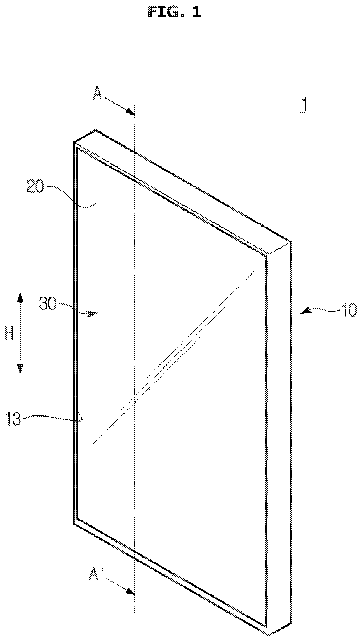
[0043]Hereinafter, embodiments of the present disclosure will be described in detail with reference to the appended drawings. In the following description, the terms “front end”, “rear end”, “upper portion”, “lower portion”, “upper end”, and “lower end” are defined based on the drawings, and the shapes and positions of the corresponding components are not limited by the terms.

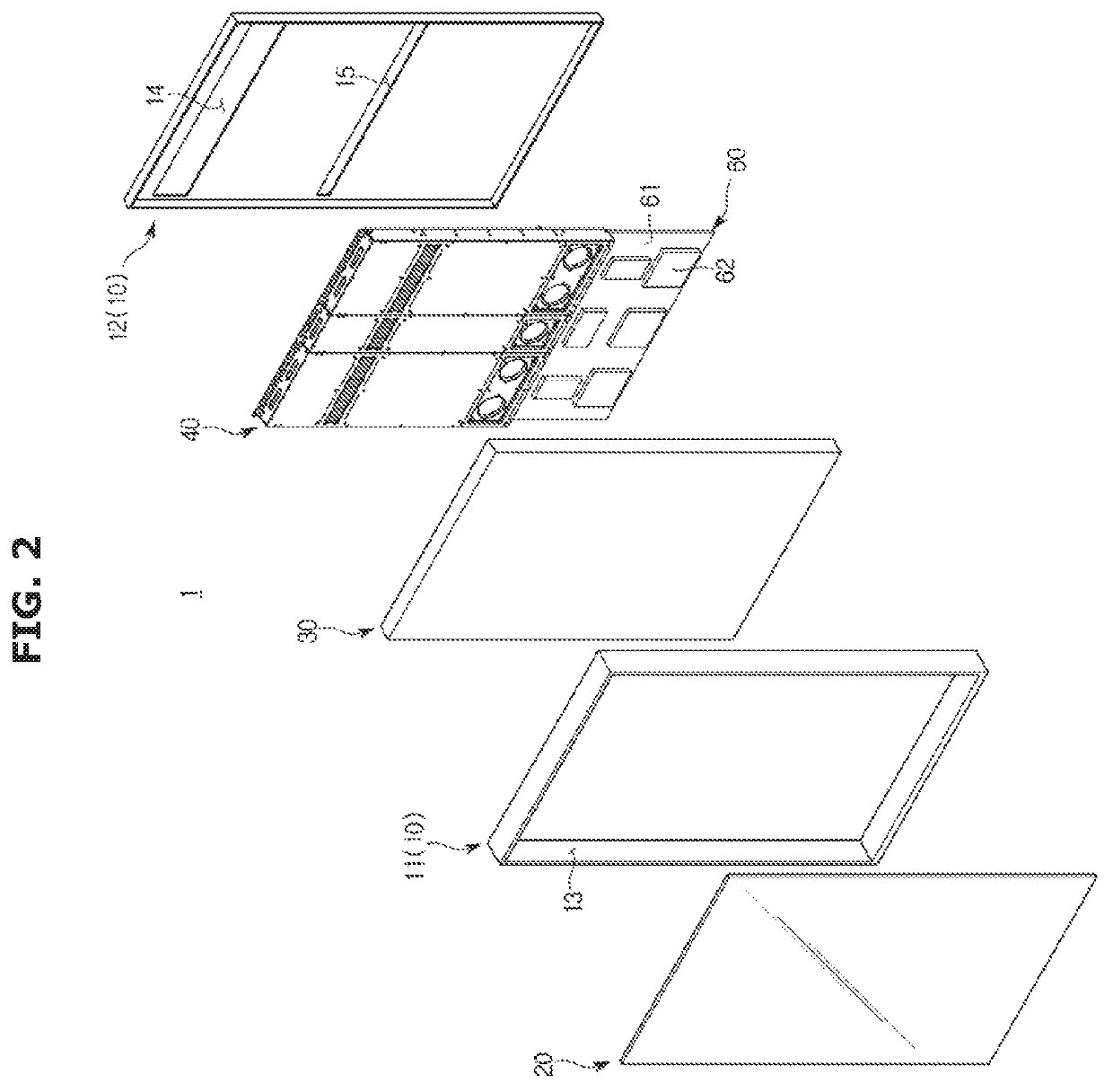
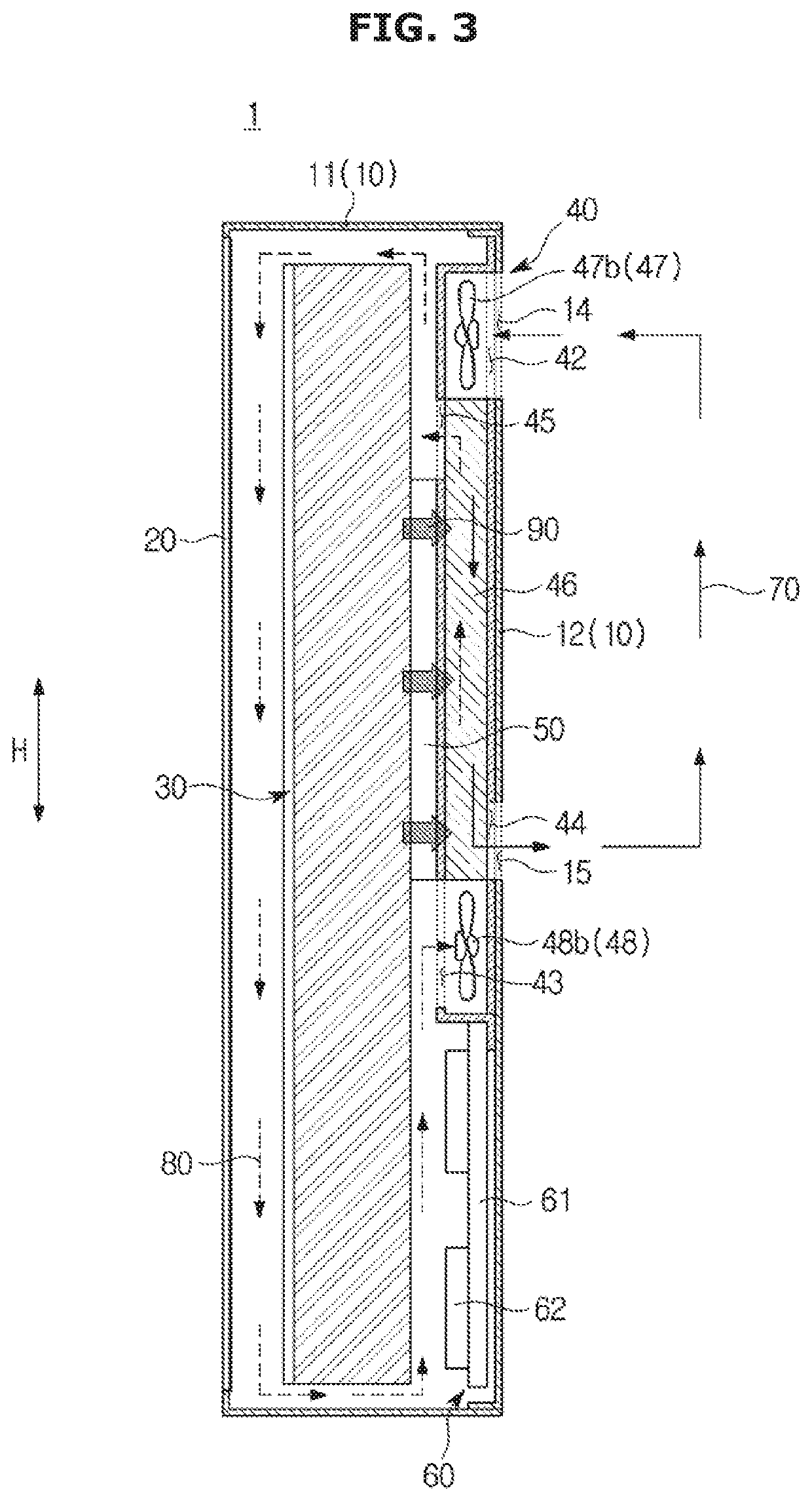
[0044]FIG. 1 is a perspective view of an outdoor display apparatus according to an exemplary embodiment, and FIG. 2 is an exploded perspective view of an outdoor display apparatus according to an exemplary embodiment. FIG. 3 is a cross-sectional view of the outdoor display apparatus of FIG. 1, taken along a line A-A′. In the following description, a cooling flow path 70 will be also referred to as a first cooling flow path 70. Also, a second heat-transfer flow path 80 will be also referred to as a second cooling flow path 80. Reference numerals not described below will be able to be understood by referring to F...


PUM

PropertyMeasurementUnit
heataaaaaaaaaa
heightaaaaaaaaaa
surface temperatureaaaaaaaaaa

Abstract

Disclosed herein is an outdoor display apparatus having a heat-radiating structure. The outdoor display apparatus includes a housing; a display module disposed inside the housing, and including a display panel on which an image is displayed; a heat-exchange module disposed on a rear surface of the display module, and configured to concentrate heat inside the housing on a rear surface of the display panel and discharge heat out of the housing; a protective glass disposed to correspond to a display area of the display panel, and configured to transmit infrared light; and a flow path formed inside the housing such that air flowing along the flow path transfers heat from the display panel to the heat-exchange module.

Description

CROSS-REFERENCE TO RELATED APPLICATION[0001]This application claims the benefit of Korean Patent Application No. 10-2016-0163760, filed on Dec. 2, 2016 in the Korean Intellectual Property Office, the disclosure of which is incorporated herein by reference in its entirety.BACKGROUND1. Field[0002]Apparatuses and methods consistent with exemplary embodiments relate to an outdoor display apparatus, and more particularly, to an outdoor display apparatus having a heat-radiating structure.2. Description of the Related Art[0003]In general, a display apparatus is equipment for displaying images on a screen, such as a television, a monitor for a computer, a digital information display, and the like. Recently, many display apparatuses are installed outdoors or outside for the purpose of advertising, etc. An example of an outdoor display apparatus is an advertising board installed on the outer wall or roof of a building to display images.[0004]In the outdoor display apparatus, if the display pa...

Claims


Application Information

Patent Timeline
Patent Type & Authority Patents(United States)
IPC IPC(8): H05K7/20G02F1/1333G09F9/35H05K5/00
CPCH05K7/20963G02F1/133308G02F1/133385G09F9/35H05K5/0017H05K7/20209G02F2001/133331G02F2203/11G02F1/133331H05K7/20972H04N5/64G06F1/20
Inventor KIM, SUNG KI
Owner SAMSUNG ELECTRONICS CO LTD
Why Eureka
Try Eureka