
Method and apparatus for removal of oxygen from seawater

a technology for oxygen removal and seawater, applied in the direction of fluid removal, water treatment parameter control, water/sludge/sewage treatment, etc., can solve the problems of large apparatus footprint, serious equipment weight, and inefficient method for offshore platforms, so as to reduce the dimensions and footprint of the apparatus

Active Publication Date: 2021-02-23
MINOX TECH
View PDF18 Cites 0 Cited by
  • Summary
  • Abstract
  • Description
  • Claims
  • Application Information

AI Technical Summary

Benefits of technology

This approach effectively reduces oxygen levels in seawater with a compact apparatus, minimizing salt deposits and operational costs, while avoiding environmental issues associated with previous methods.

Problems solved by technology

However, this method requires a large tower and the apparatus has a large footprint.
This method is inefficient for use at offshore platforms where space is at a minimum and weight of the equipment might be a serious problem.
The used fuel gas must either be treated in a separate system or in many cases flared and by that have a negative effect on the environment.
Further, the method has high operating costs.
However, chemicals used as scavengers are expensive and significantly affect the cost of operating a seawater injection system.
However, the use of the method requires incorporation of apparatuses and processes for remediation of operating problems that can arise, including, for example, foaming and entrainment that cause fouling of the downstream equipment, and so affect performance of the overall process.
Another drawback with this method and apparatus is that use of conventional gravity separators result in a larger footprint and heavier weight than what can be achieved by present invention.
A problem that can occur with the recycle system of this type is that the catalyst and other equipment in the gas loop are prone to fouling from entrained saltwater.

Method used


Image

  • Method and apparatus for removal of oxygen from seawater

Examples


Embodiment Construction

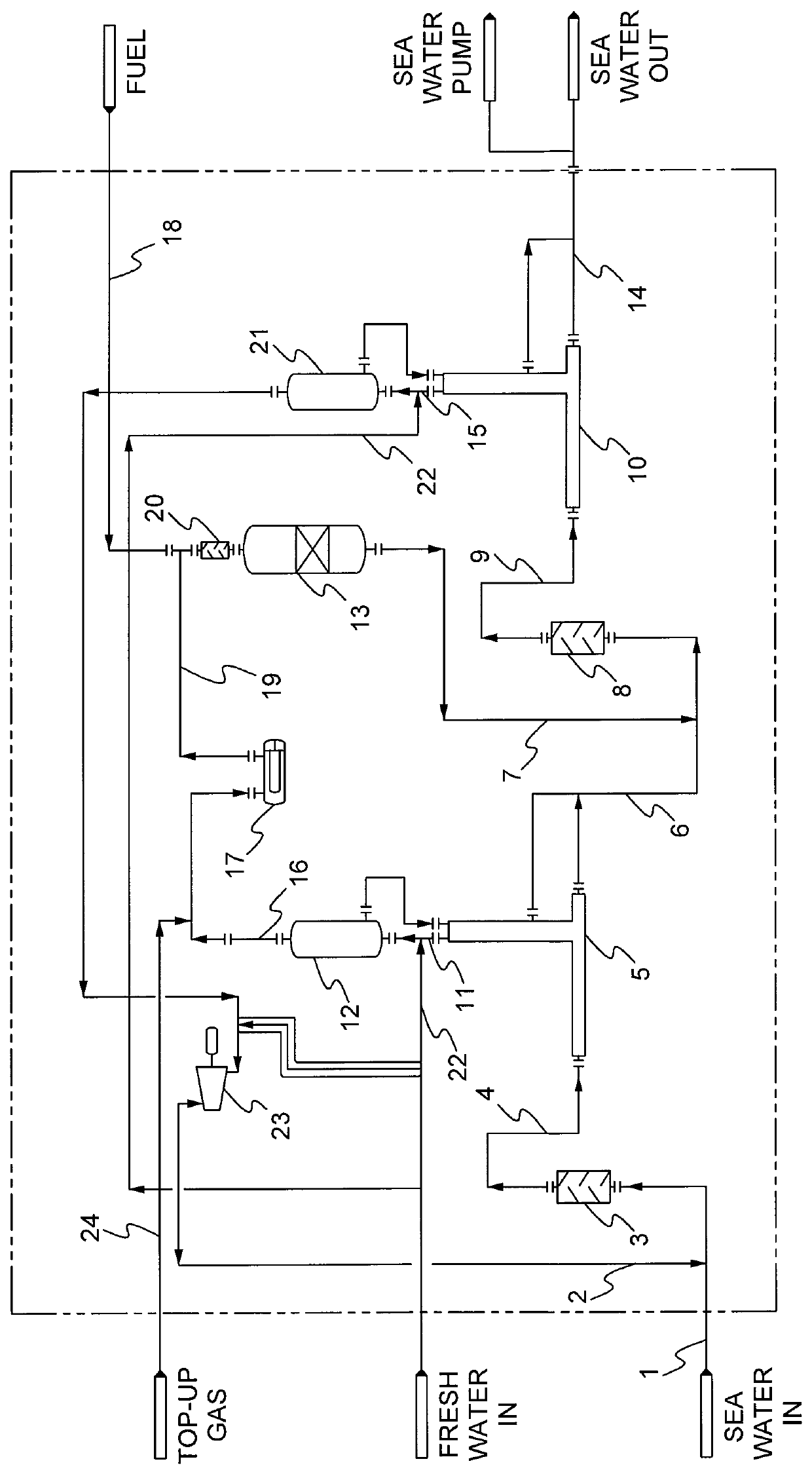
[0043]FIG. 1 shows a preferred embodiment of the system according to the invention. A seawater stream (1) to be deaerated is mixed with a stripping gas stream (2), for example, but not limited to nitrogen, circulated by a compressor or blower (23). This two-phase stream is led through a first stage static mixer (3), providing contact area and turbulent mixing, resulting in oxygen transfer from the liquid to the gas. Typical operating conditions for the static mixer (3) is a pressure of 3-10 barg and a temperature of 0-50° C. The mixed stream (4), containing water, stripping gas, oxygen and salt, is led to a first stage inline separator (5). The first stage inline separator (5) separates gas / water into gas phase (11) and liquid phase (6). Typical operating conditions for the separator (5) is a pressure of 2-10 barg and a temperature of 0-50° C. The gas stream from the inline separator (11) contains stripping gas, oxygen, some water, both vapour and entrained liquid droplets including...


PUM

PropertyMeasurementUnit
temperatureaaaaaaaaaa
pressureaaaaaaaaaa

Abstract

Method for removal of oxygen from seawater includes leading a stream of seawater and a pressurized stripping gas to a first mixer, mixing the seawater with stripping gas, leading the combined stream to a first gas / liquid inline separator, separating the stream into a liquid rich and a gas rich phase, leading the liquid stream and a stripping gas stream to a second mixer, mixing the liquid stream with the gas stream, leading the combined stream to a second stage inline separator, separating the combined stream into a liquid- and gas-rich phases, mixing the gas stream with a fresh water stream, leading this combined stream to a first stage scrubber, removing a portion of the salt entrained in the combined stream from the scrubber, and leading the salt depleted gas stream from the first scrubber via a heat exchanger or electrical preheater together with a fuel stream to a catalytic deoxidizer.

Description

[0001]Present invention relates to a method and apparatus for removal of oxygen from seawater according to the preamble of the independent claims.TECHNICAL FIELD[0002]Present invention relates to a method and apparatus for removal of dissolved oxygen in seawater to be injected under high pressure into an oil and / or gas reservoir for enhanced oil and / or gas recovery.[0003]Oil and / or gas can be recovered from subsea reservoirs by means of the natural occurring pressure in the reservoir. Additional oil and / or gas can be received by injecting seawater in order to force more oil and / or gas out of the reservoir. In untreated seawater, there is dissolved oxygen, and this oxygen has to be removed in order to avoid corrosion problems in the equipment and also to reduce bacterial growth in the reservoir. The amount of oxygen dissolved in the seawater is temperature dependent.BACKGROUND ART[0004]Several methods and apparatuses for reduction of oxygen in seawater for injection into and oil and / ...

Claims


Application Information

Patent Timeline
Patent Type & Authority Patents(United States)
IPC IPC(8): C02F1/20B01D19/00E21B43/20C02F103/08C02F1/02C02F1/70
CPCC02F1/20B01D19/0005B01D19/0015C02F1/02C02F1/70C02F2103/08C02F2209/02C02F2209/03C02F2209/22E21B43/20B01D19/00B01D19/0042C02F1/725E21B43/00
Inventor FRIIS, TOR SKOVDALSISJORD, INGVILD LINDHEIM
Owner MINOX TECH
Learn More