Execution unit accelerator
a technology of execution unit and accelerator, applied in the field of graphics processing, can solve the problems of several years to incorporate, lack of flexibility in executing instructions associated with new formats,
Active Publication Date: 2021-02-23
INTEL CORP
View PDF3 Cites 0 Cited by
- Summary
- Abstract
- Description
- Claims
- Application Information
AI Technical Summary
Benefits of technology
The present invention relates to a system and method for accelerating the execution of graphics processing units (GPUs) in order to improve their performance and flexibility. The invention provides an accelerator that can be integrated into a processing system, such as a server, game console, or mobile device, to perform programmable operations. The accelerator includes a pipeline of execution units, with each unit designed to execute a specific task. The invention allows for the flexibility to easily incorporate new formats and instructions, improving the speed and efficiency of GPUs.
Problems solved by technology
However, EUs lack a flexibility of executing instructions associated with new formats.
For example, a content provider that develops a new video format is unable to implement the format until associated logic to execute the format is programmed into the EU hardware, which may take several years to incorporate.
Method used
View moreImage
Smart ImageViewing Examples
Examples
example 2
[0202 includes the subject matter of Example 1, wherein the accelerator updates a target register in the register file with a result of the performed operation.
example 3
[0203 includes the subject matter of Examples 1 and 2, wherein the programmable hardware comprises one or more micro programmable gate arrays (uFPGAs).
example 4
[0204 includes the subject matter of Examples 1-3, wherein the one or more uFPGAs comprise one or more Adaptive Logic Modules and a memory.
Login to View More PUM
 Abstract
A processor to facilitate acceleration of instruction execution is disclosed. The processor includes a plurality of execution units (EUs), each including an instruction decode unit to decode an instruction into one or more operands and opcode defining an operation to be performed at an accelerator, a register file having a plurality of registers to store the one or more operands and an accelerator having programmable hardware to retrieve the one or more operands from the register file and perform the operation on the one or more operands.
Description
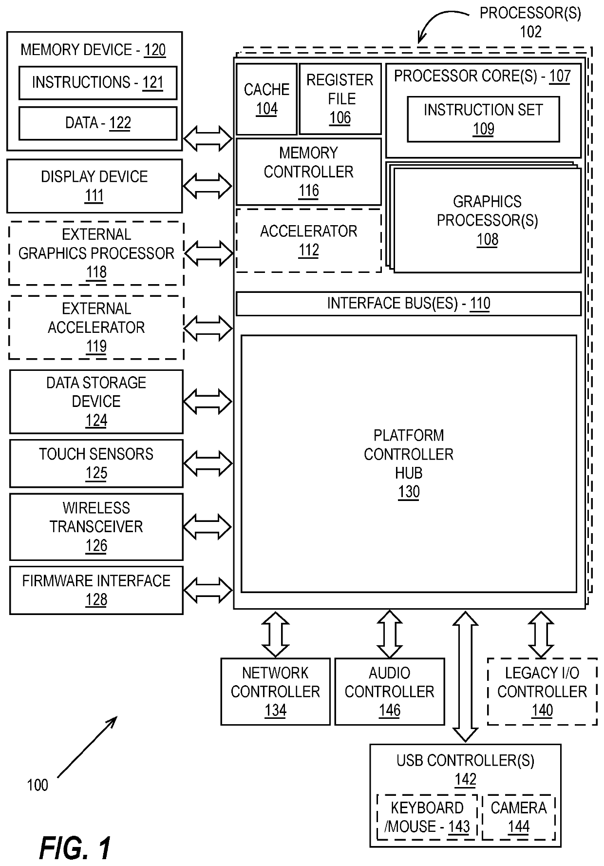
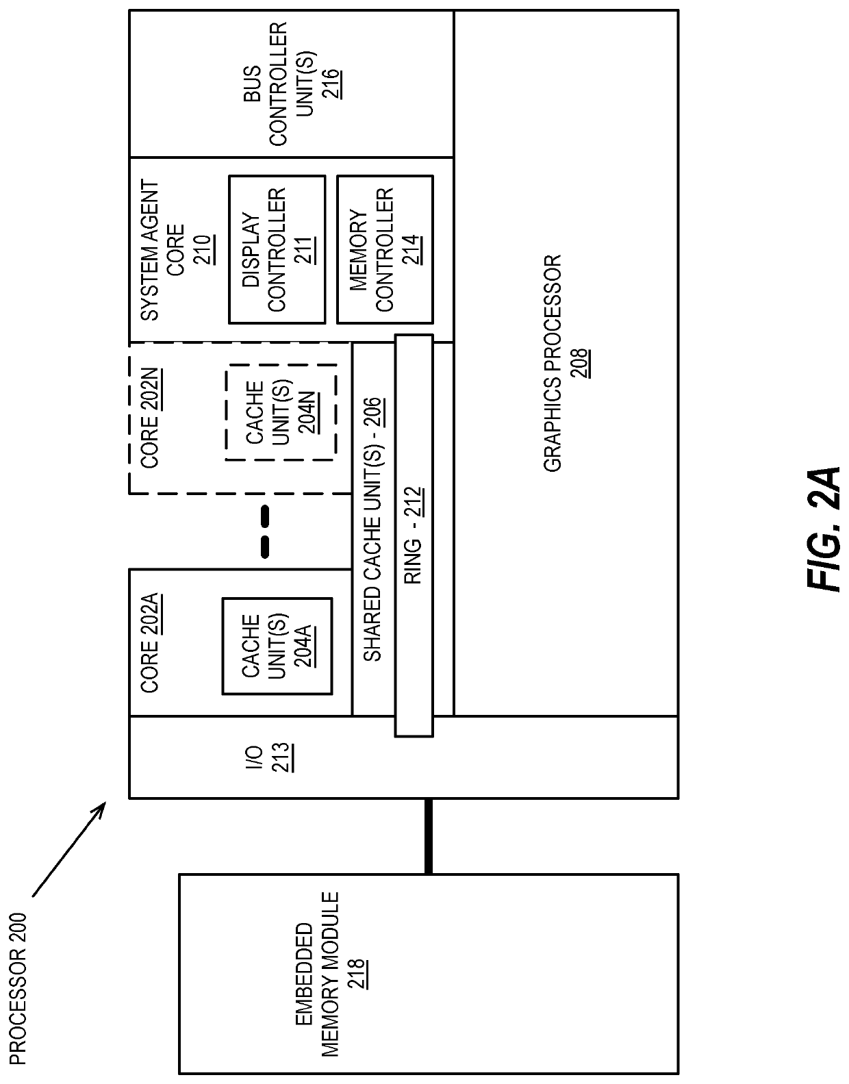
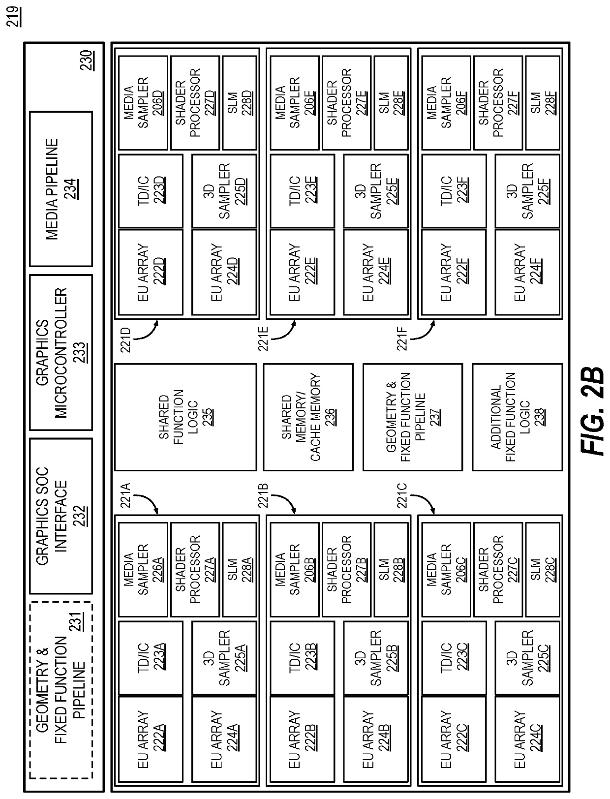
FIELD OF INVENTION[0001]This invention relates generally to graphics processing and more particularly to accelerating execution of a graphics pipelines.BACKGROUND OF THE DESCRIPTION[0002]Graphics processing units (GPUs) are highly threaded machines in which hundreds of threads of a program are executed in parallel to achieve high throughput. In some implementations, threads may be organized into a collection (e.g., 7 or 8 threads) depending on generation, and are assigned to one of several Execution Unit (EUs) within the GPU. An EU typically includes general purpose registers to hold variables used while running graphics or compute kernels. However, EUs lack a flexibility of executing instructions associated with new formats. For example, a content provider that develops a new video format is unable to implement the format until associated logic to execute the format is programmed into the EU hardware, which may take several years to incorporate.BRIEF DESCRIPTION OF THE DRAWINGS[000...
Claims
Login to View More Application Information
Patent Timeline
 Patent Type & Authority Patents(United States)
IPC IPC(8): G06T1/20G06F9/30
CPCG06F9/3016G06F9/3001G06T1/20G06F9/30145G06F9/3822
Inventor SRIPADA, RADHAKRISHNAYIANNACOURAS, PETERTRIPLETT, JOSHCHITLUR, NAGABHUSHANKONDAPALLY, KALYAN
Owner INTEL CORP
Features
- R&D
- Intellectual Property
- Life Sciences
- Materials
- Tech Scout
- Unparalleled Data Quality
- Higher Quality Content
- 60% Fewer Hallucinations
Learn More Browse by: Latest US Patents, China's latest patents, Technical Efficacy Thesaurus, Application Domain, Technology Topic, Popular Technical Reports.
© 2025 PatSnap. All rights reserved.Legal|Privacy policy|Modern Slavery Act Transparency Statement|Sitemap|About US| Contact US: help@patsnap.com


