Indicator member of low strength resistance for a tamper evident closure

a technology of indicator member and low strength resistance, which is applied in the direction of packaging, packaging foodstuffs, packaged goods, etc., can solve the problems that the tip cap, when connected to the syringe or medical device, cannot freely pass through the access opening to the exterior of the housing, and achieve the effect of facilitating the peeling of the cover and facilitating the establishment and maintenance of a sterile environmen

Active Publication Date: 2021-03-02
INT MEDICAL INDS
View PDF357 Cites 14 Cited by
  • Summary
  • Abstract
  • Description
  • Claims
  • Application Information

AI Technical Summary

Benefits of technology

[0015]Yet additional features of the one or more preferred embodiments of the tamper evident closure includes a cover interconnected to the housing by being attached to the housing or to a portion of the indicator member such as, but not limited to, the outer segment thereof. Therefore, the cover is disposed in overlying, covering relation to at least a portion of the indicator member and in covering relation to the access opening. Attachment of the cover in this preferred position may be accomplished by a removable adhesive which facilitates the cover being peeled away from its overlying, covering position to the access opening and indicator member.
[0016]In order to facilitate the establishment and maintenance of a sterile environment of at least the tip and / or the interior of the housing, the cover may be at least partially formed from a gas permeable material, such as but not limited to Tyvek®, which allows a sterilizing gas medium to pass there through. Such a sterilizing gas may be in the form of ethylene trioxide (ETO) or other appropriate sterilizing medium.

Problems solved by technology

As a result, the tip cap, when connected to the syringe or medical device, will not be able to freely pass back through the access opening to an exterior of the housing, due to the comparative smaller transverse dimension of the access opening relative to the tip cap.

Method used


Image

  • Indicator member of low strength resistance for a tamper evident closure
  • Indicator member of low strength resistance for a tamper evident closure
  • Indicator member of low strength resistance for a tamper evident closure

Examples


Embodiment Construction

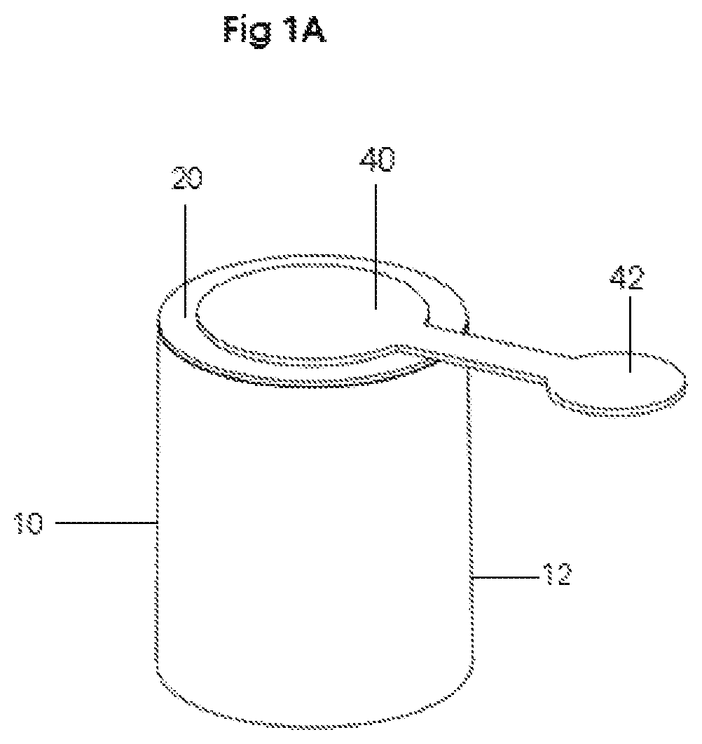
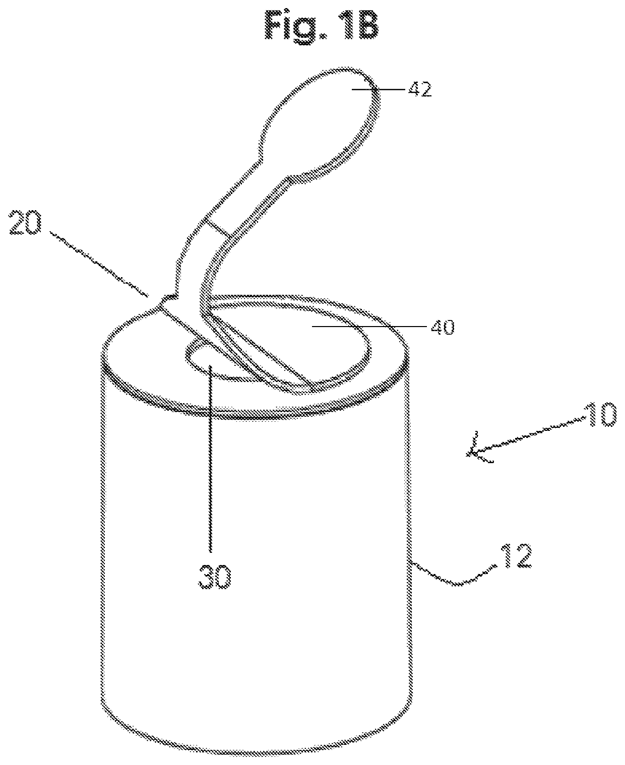
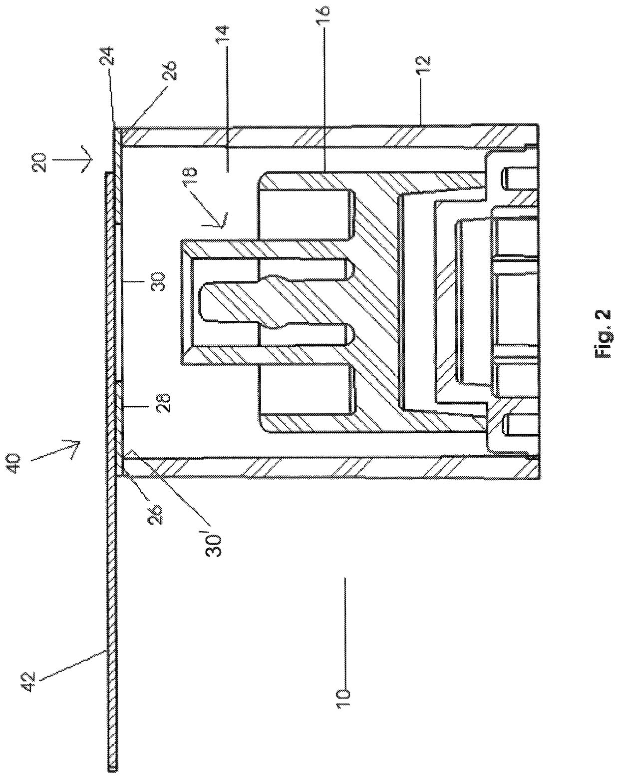
[0027]As represented throughout the accompanying Figures, the present invention is directed to a tamper evident closure generally indicated as 10. The tamper evident closure 10 includes an external housing 12 having a substantially hollow interior 14, as partially shown in FIG. 1B, and more clearly represented in FIG. 2. The housing or sleeve 12 includes a closed end or bottom, which may be formed by a single injection mold which will help in terms of saving both expense and assembly time.

[0028]In addition, the tamper evident closure 10 includes a closure, preferably in the form of a tip cap 16, shown in FIGS. 2 and 4, that is removably disposed within the interior 14 of the housing 12. As indicated in FIG. 2 and described subsequently herein, the tip cap 16 may also be movably disposed within the housing 12.

[0029]With reference to FIG. 2, the tip cap 16 may be structured to include a luer connector, preferably in the form of a luer-slip connector generally indicated as 18, as also ...


PUM


Abstract

A tamper evident closure, intended primarily for a luer-slip or like frictional connection between one or more components associated with the closure and a syringe or other medical device, includes a housing having an open end and a tip cap disposed within the housing. An indicator member is connected to the housing in at least partially covering relation to the open end and includes an access opening disposed in accessible relation with the tip cap. A cover is removably disposed in overlying engagement with at least a portion of said indicator member in covering relation to the access opening. The indicator member has an inner segment disposed in contiguous surrounding relation to the access opening and has a reduced breakaway resistance, capable of being easily ruptured, ripped or torn during passage of said tip cap through the access opening, concurrent to the tip cap being connected to the medical device.

Description

CLAIM OF PRIORITY[0001]The present application is based on and a claim of priority is made under 35 U.S.C. Section 119(e) to a provisional patent application that is currently in the U.S. Patent and Trademark Office, namely, that having Ser. No. 62 / 508,638 and a filing date of May 19, 2017, which is incorporated herein by reference in its entirety.BACKGROUND OF THE INVENTIONField of the Invention[0002]This invention is directed to a tamper evident closure for a medical device which includes an indicator member disposed in overlying relation to an open end of the housing. At least a portion of the indicator member comprises a material having a predetermined low-strength breakaway resistance, which is easily ruptured upon removal of a tip cap from the interior of the housing, concurrent to its being frictionally connected to a medical device.Description of the Related Art[0003]In the medical field, it is a relatively common for authorized medical personnel to prescribe a drug or medic...

Claims


Application Information

Patent Timeline
Patent Type & Authority Patents(United States)
IPC IPC(8): A61M5/50A61J1/20A61M5/31
CPCA61M5/5086A61J1/2096A61M2005/312A61M5/50A61M2005/3104A61M2005/3106
Inventor BANIK, ROBERT
Owner INT MEDICAL INDS
Why Eureka
Try Eureka