Membrane filter device

a membrane filter and membrane technology, applied in the field of efficient and steadfast filtration devices, can solve the problems of large total membrane system, large membrane size, high energy consumption and fluid flow, etc., and achieve the effects of easy assembly and disassembly, cost-effective, and energy-saving

Active Publication Date: 2021-03-02
KING ABDULAZIZ UNIV
View PDF12 Cites 4 Cited by
  • Summary
  • Abstract
  • Description
  • Claims
  • Application Information

AI Technical Summary

Benefits of technology

[0015]It is a further objective of the present invention to provide a membrane and filter testing device which is cost-effective.
[0016]It is another objective of the present invention to provide a membrane and filter testing device which is energy efficient and user friendly and can be assembled and detached easily.
[0017]It is another objective of the present invention to provide a filtration device that is useful from small applications to large applications.
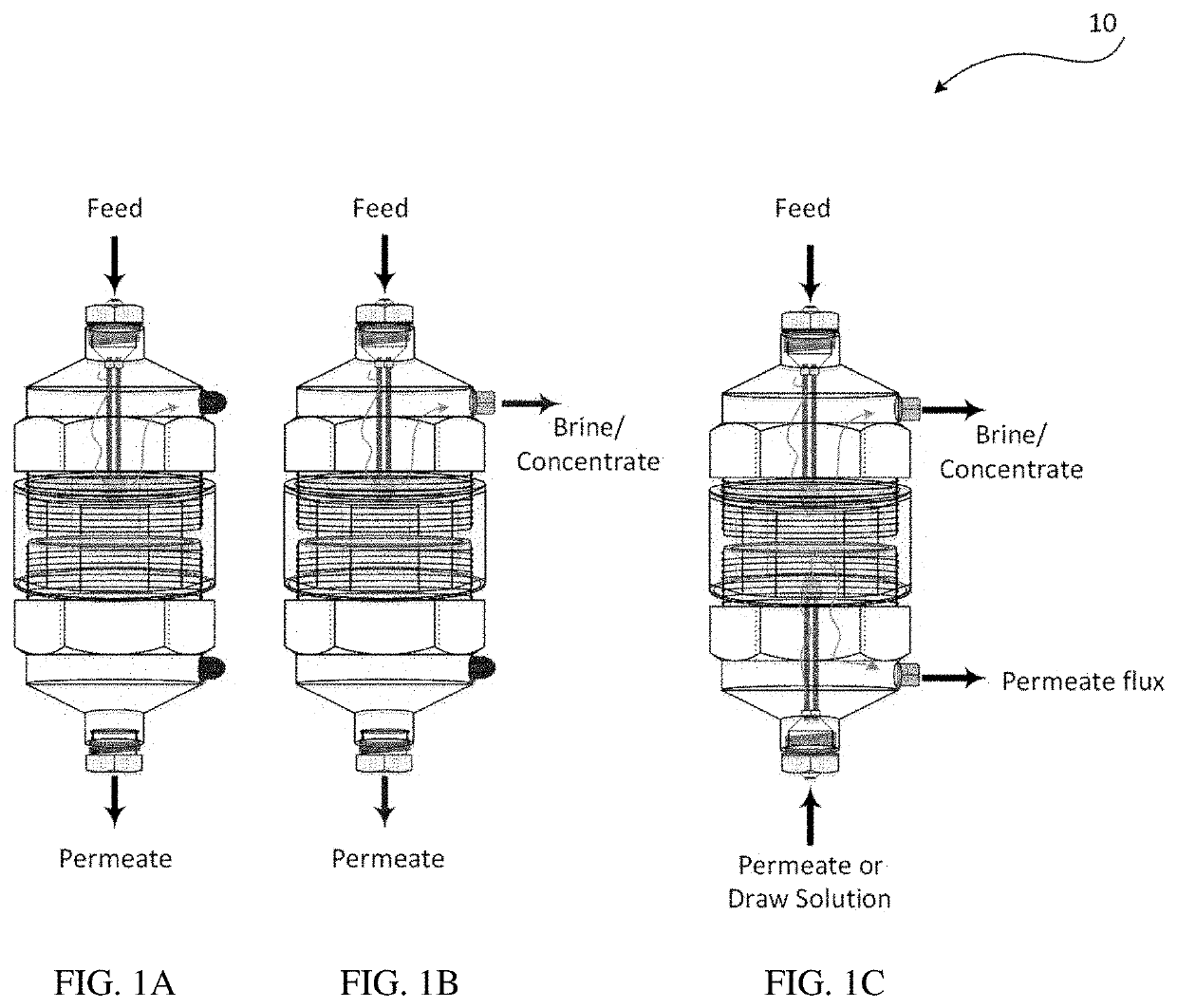
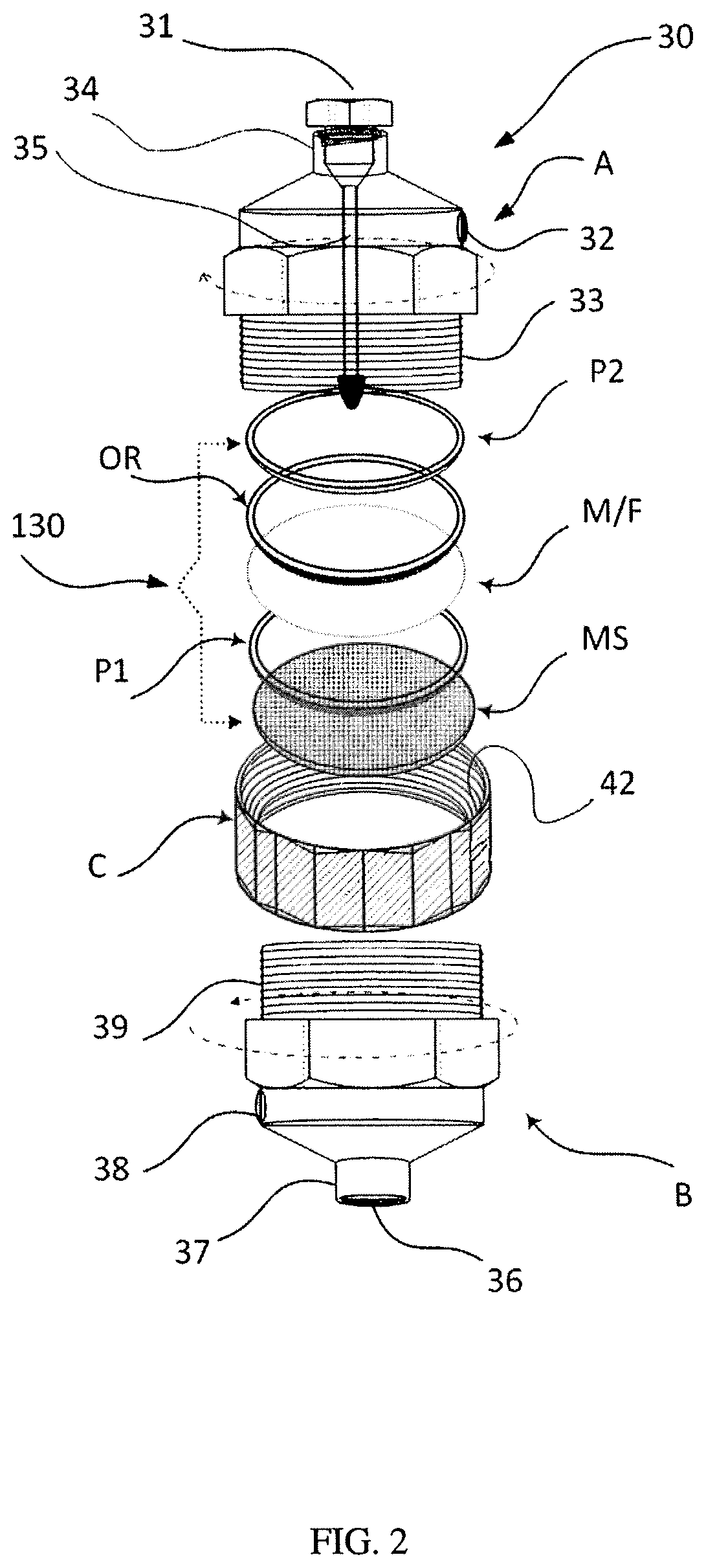
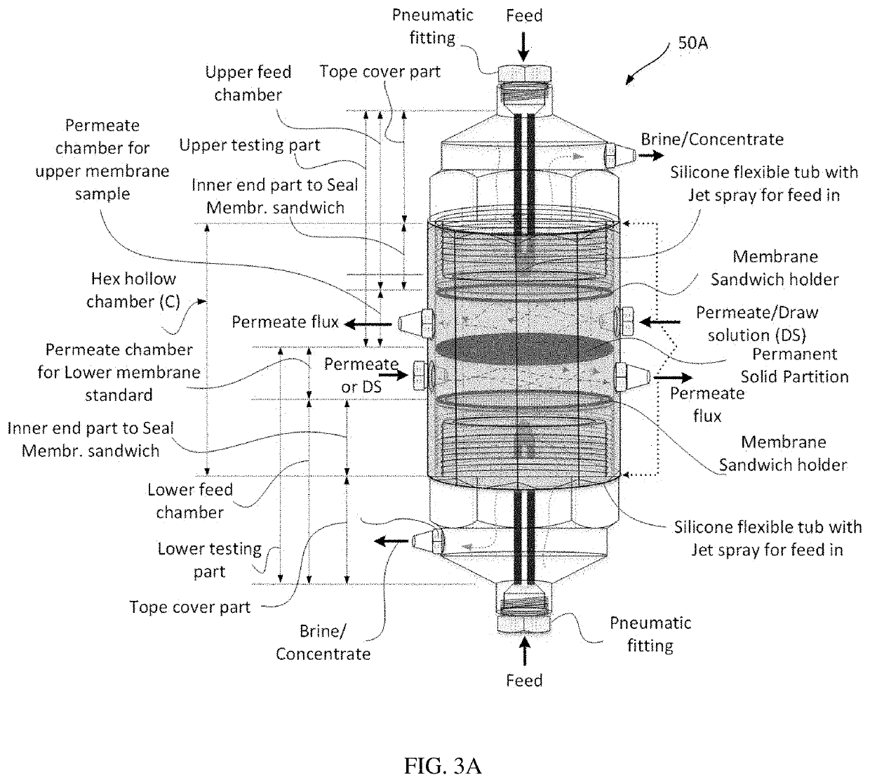
[0018]Accordingly, these objectives may be achieved by following the teachings of the present invention. In some embodiments, the present invention relates to a membrane filter device comprising a cell top cover and a cell bottom cover covering the device, a flexible tube for distributing the feel fluid, a feed chamber for storing and receiving feed fluid, a reducer chamber for storing and receiving permeate filtrated fluid, a connector connecting both feed chamber and reducer chamber, a membrane assembly comprising a layer of membrane sandwiched by a pair of seal rings and a layer of support net for securing said membrane. Most of the joints are connected using threaded joint and flow pressure therefore no external clamp, no nut and bold is needed. The flexible pipe and the cylindrical shape ensure uniform flow in chambers. The present invention is therefore a user-friendly and reliable membrane test device.

Problems solved by technology

A complete membrane system is generally huge, requires high energy consumption and high fluid flow as well as bigger membrane size.
Therefore, testing of a membrane in this full-size membrane system can be very expensive.
However, several of these cells have one or more problems or limitations.
However, the membrane test unit has a major drawback which is uneven feed fluid velocity and pressure in the feed spacer cavity.
Another problem is the hydraulic clamp which causes undesired flow of water towards the permeate cavity.
The device requires a relatively expensive hydraulic pump in order for the system to function which is not cost-effective.
Therefore, the cited patent is not cost effective as for every test carried out, a new cassette is required.
However, this causes the cited apparatus to be hard to assemble and detach.
Additionally, the cited apparatus is big in size which is not convenient and takes up a lot of space for example in a small lab.

Method used


Image

  • Membrane filter device
  • Membrane filter device
  • Membrane filter device

Examples


Embodiment Construction

[0027]As required, detailed embodiments of the present invention are disclosed herein; however, it is to be understood that the disclosed embodiments are merely exemplary of the invention, which may be embodied in various forms. Therefore, specific structural and functional details disclosed herein are not to be interpreted as limiting but merely as a basis for claims. It should be understood that the drawings and detailed description thereto are not intended to limit the invention to the particular form disclosed, but on the contrary, the invention is to cover all modification, equivalents and alternatives falling within the spirit and scope of the present invention as defined by the appended claims. As used throughout this application, the word “may” be used in a permissive sense (i.e., meaning having the potential to), rather than the mandatory sense (i.e., meaning must). Similarly, the words “include,”“including,” and “includes” mean including, but not limited to. Further, the w...


PUM

PropertyMeasurementUnit
flexibleaaaaaaaaaa
shapeaaaaaaaaaa
particle sizesaaaaaaaaaa

Abstract

Provided herein is a membrane filter device comprising a cell top cover (A, Y) and a cell bottom cover (B, Z) covering the device, a flexible tube (35, E, F) whereas at the end of the tube, a nozzle jet (22) is also secured via conical reducer to produce upper Reynold's number and for distributing the feed fluid, within the hex hollow chamber (C, X) for storing and receiving feed fluid, a reducer chamber (C, R1, R2) for storing and receiving permeate filtrated fluid, a connector (32, 53, 56) connecting both feed chambers (A, Y, Z) and reducer chambers (A, Y, Z), a membrane assembly (M/F) comprising a layer of membrane (130) sandwiched by a pair of seal rings (P1, OR, P2) and a layer of support net (MS) for securing said membrane (M/F). Most of the joints are connected using threaded joint and flow pressure, therefore no external clamp, nuts or bolts is needed. The flexible tube and the cylindrical shape ensure uniform flow in chambers. The apparatus is therefore a user-friendly and steadfast membrane filter device.

Description

BACKGROUND OF THE INVENTIONField of the Invention[0001]The present invention relates to an efficient and steadfast filtration device, more particularly a membrane filter device.Description of Related Arts[0002]Filtration systems are widely used for separation of impurities from fluid for example in water purifications, beverage processing, wastewater treatment and other separation applications. This is usually done by interposing a medium such as a semi-permeable or permeable membrane through which only fluid with smaller particle sizes can pass in order to reject impurities (substances) from the fluid. In a general setup of a membrane system, a pump forces the contaminated fluid towards the membrane. A small amount of fluid permeates the membrane as a product fluid while the remaining fluid portions will leave the module as concentrated fluid. The membranes are of different materials, characteristics, various pore sizes and distribution in order to reject different sizes and types ...

Claims


Application Information

Patent Timeline
Patent Type & Authority Patents(United States)
IPC IPC(8): G01N1/40B01D63/06B01D61/36B01D61/28B01D61/18B01D61/08B01D63/08B01D69/10B01D69/06B01D69/04
CPCG01N1/40B01D61/08B01D61/18B01D61/28B01D61/366B01D63/063B01D63/065B01D63/087B01D69/04B01D69/06B01D69/10B01D2311/14B01D2311/16B01D2313/025B01D2313/04B01D2313/08B01D2313/14B01D2313/143B01D2313/20B01D2313/21B01D2313/22G01N2015/084G01N2001/4088G01N15/082B01D61/002B01D2315/08B01D65/10B01D2313/201B01D2313/205
Inventor MOUJDIN, IQBAL AHMED
Owner KING ABDULAZIZ UNIV
Why Eureka
Try Eureka