Test system and method with a thermally isolated hollow body inside an over the air measurement chamber

a test system and hollow body technology, applied in the direction of electronic circuit testing, measurement devices, instruments, etc., can solve the problem that temperature is not suitable for the measurement equipment required, and achieve the effect of reducing temperature loss and manufacturing effor

Active Publication Date: 2021-03-02
ROHDE & SCHWARZ GMBH & CO KG
View PDF11 Cites 0 Cited by
  • Summary
  • Abstract
  • Description
  • Claims
  • Application Information

AI Technical Summary

Benefits of technology

[0009]Advantageously, a thermally isolated hollow body is provided within an OTA measurement chamber to ensure that the temperature of the air within the hollow body is not influenced by the temperature within the OTA measurement chamber and vice versa. It might be required to test a device under test (DUT) at low temperatures, preferably up to minus 40 degrees Celsius (−40° C.) and at high temperatures, preferably up to plus 85 degrees Celsius (+85° C.). Such temperatures are not suitable for measurement equipment required to perform the OTA measurements. By providing a thermally isolated hollow body and positioning the DUT within said body, the DUT can be tested at high and low temperatures without influencing the temperature within the OTA measurement chamber containing measurement equipment. Moreover, since the volume of the thermally isolated hollow body can be adapted to the size of the DUT and therefore the volume can be reduced compared to the volume of the overall OTA measurement chamber, stable ambient conditions can be reached much faster inside the smaller volume.
[0011]Furthermore, the thermally isolated hollow body ensures that stable ambient conditions such as stable temperatures can be reached, since no temperature loss due to the thermally isolated hollow body can take place.
[0012]It is further advantageous that the same opening in the thermally isolated hollow body is used for two different applications. On the one hand, the opening is used to connect an air hose to the thermally isolated hollow body and on the other hand, the same opening is used to guide a sensor connection wire preferably the wire including the sensor through said opening. Thus, less openings are required to be drilled into or provided with the thermally isolated hollow body, which reduces temperature losses and manufacturing effort. Every additional opening in the thermally isolated hollow body increases the probability that an unwanted temperature exchange between the air within the thermally isolated hollow body and the air within the OTA measurement chamber takes place through said additional opening.
[0017]Advantageously, the sensor connection wire that enters the feedthrough from the outside of the OTA measurement chamber at a separate location than the air hose is put into the air hose inside the feedthrough. To put the sensor connection wire into the air hose requires to make a small opening, exemplarily a hole into the air hose, which results in a leakage that would cause air within the air hose to exit the air hose or to cause air flowing from the outside of the hose into said hose. However, since the sensor connection wire is put into the hole in the air hose within the feedthrough, the feedthrough serves as a kind of seal and prevents that air leaves the air hose or that air gets inside the air hose through said hole. Thus, no additional means are required to seal the opening, respectively the hole in the air hose after having inserted the sensor connection wire.
[0037]Advantageously, the heated and / or cooled air generator is capable of reducing the humidity level and / or the condensation level of the air circulating within the system consisting of the thermally isolated hollow body, the two air hoses and the heated and / or cooled air generator. Thus, the humidity level and / or the condensation level of the air supplied into the thermally isolated hollow body can be controlled. When a certain humidity level and / or condensation level is exceeded, which is sensed by the humidity sensor and converted into appropriate sensor signals transmitted to the heated arid / or cooled air generator, the air passing through the heated and / or cooled air generator is heated up and cooled down to reduce the humidity and / or the condensation.

Problems solved by technology

Such temperatures are not suitable for measurement equipment required to perform the OTA measurements.

Method used


Image

  • Test system and method with a thermally isolated hollow body inside an over the air measurement chamber
  • Test system and method with a thermally isolated hollow body inside an over the air measurement chamber
  • Test system and method with a thermally isolated hollow body inside an over the air measurement chamber

Examples


Embodiment Construction

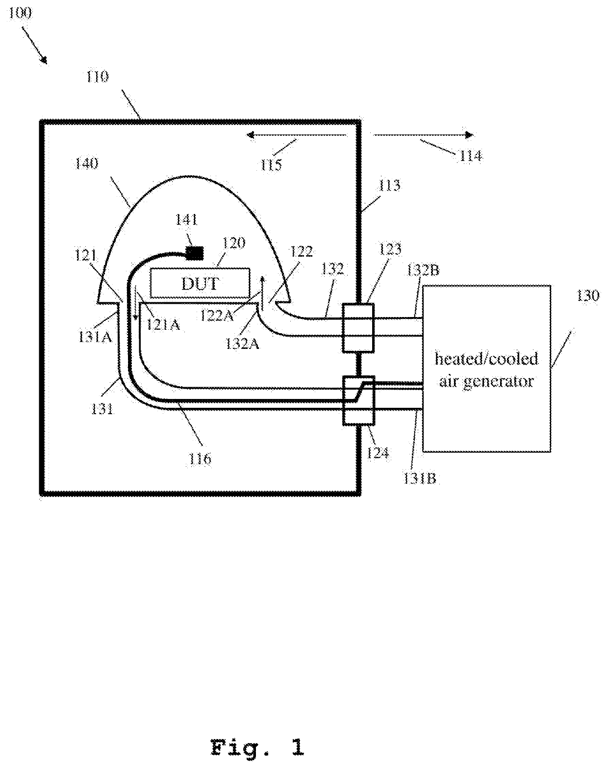
[0049]FIG. 1 illustrates a block diagram of the inventive over-the-air (OTA) test system for measuring a performance of a device under test (DUT).

[0050]Typical OTA test systems, especially OTA performance test systems are used to analyze and optimize the radiated device performance and to validate conformance with industry, network operator and internal company requirements. Specifically, the antenna patterns as well as the transmitter and receiver chain wireless system performance such as Total Radiated Power (TRP), Total Isotropic Sensitivity (TIS) or Total Radiated Sensitivity (TRS), respectively, are verified with an OTA test system. These measurements follow test plans and detailed test and setup procedures published by industry organizations such as Cellular Telecommunications and Internet Association (CTIA) and 3rd Generation Partnership Project (3GPP). Such OTA test systems include an anechoic chamber, positioning equipment, test instruments and automated measurement, softwa...


PUM


Abstract

The invention relates to an over-the-air (OTA) test system for measuring a performance of a device under test (DUT). The test system comprises an over-the-air (OTA) measurement chamber provided with at least one feedthrough for at least a first air hose and a second air hose. The test system further includes a thermally isolated hollow body inside the OTA measurement chamber, in which the DUT is positioned having at least two openings for connecting a first end of each of the first and the second air hose, and at least one sensor having a connection wire, located within the thermally isolated hollow body. Advantageously, the sensor connection wire is fed through one of the two openings into the thermally isolated hollow body.

Description

TECHNICAL FIELD[0001]The invention relates to an over-the-air test system and method for measuring a performance of a device under test (DUT). The test system comprises an over-the-air (OTA) measurement chamber provided with at least one feedthrough for at least a first air hose and a second air hose.BACKGROUND ART[0002]Over the last years, the use of wireless communication applications has increased tremendously and will further increase. Generally, wireless, enabled devices have to pass a variety of industry and regulatory certifications before they can be put on the marked. Performance testing such as OTA (Over-The-Air) measurement is one important measurement required for said wireless devices. OTA measurements are specifically performed to measure antenna patterns and include the measurement of the radiated transmit power (TRP) of a device under test at incremental locations surrounding the device.[0003]Since wireless communication applications are exposed to different ambient ...

Claims


Application Information

Patent Timeline
Patent Type & Authority Patents(United States)
IPC IPC(8): G01R31/28G01R29/10G01R31/00
CPCG01R31/2874G01R29/105G01R31/003G01R29/0821
Inventor ROWELL, CORBETTULLRICH, STEFANKUEHLING, HEIKO
Owner ROHDE & SCHWARZ GMBH & CO KG
Why Eureka
Try Eureka