Rotationally stabilized contact lens

a technology of rotating stabilizer and contact lens, which is applied in the field of rotating stabilized contact lens, can solve the problems of less than ideal alignment of contact lenses on the eye, prior approaches to stabilization being less than ideally suited for use with accommodating contact lenses, and inability to adjust the angle of contact lenses, etc., to achieve the effect of improving the stabilization of contact lenses, reducing thickness, and reducing thickness

Active Publication Date: 2021-03-09
ONEFOCUS VISION
View PDF30 Cites 1 Cited by
  • Summary
  • Abstract
  • Description
  • Claims
  • Application Information

AI Technical Summary

Benefits of technology

[0008]The stabilized contact lens methods and apparatus disclosed herein provide improved stabilization of a contact lens placed on a cornea of an eye. The contact lens comprises stabilization zones that allow the lens to repeatedly and consistently orient on the cornea such that a sensing zone located on the lower portion of the lens is located inferiorly to engage the lower eyelid. Although specific reference is made to an accommodating contact lens with a fluidic module, the embodiments disclosed herein can be used with any contact lens where stabilization is helpful. The stabilized contact lens can provide a lower pressure sensing zone with decreased thickness for pressure or other sensing related to the lower eyelid. The decreased thickness has the advantage of improving coupling between forces from an eyelid and a lower chamber of a fluidic module. The improved coupling allows increased amounts of fluid to move between the lower chamber and an upper optical chamber coupled to the lower chamber, such that the upper chamber can increase curvature and optical power in response to pressures of the eyelid. The improved stabilization helps to maintain the lower chamber toward the lower eyelid. The improved stabilization can be provided with an upper stabilization zone and a zone of increased thickness having increased thickness relative to the upper stabilization zone. The pressure sensing zone can be located over the lower chamber with decreased thickness relative to the zone of increased thickness to improve coupling of the pressure sensing zone to the lower eyelid. The stabilization provided with the upper stabilization zone and the zone of increased thickness can be sufficient to stabilize the lens with the decreased mass of the sensing zone. Each of the upper stabilization zone, the zone of increased thickness, and the pressure sensing zone may comprise fillets defining boundaries of the corresponding zones. The fillet boundaries can be arranged to provide stabilization, and may comprise portions of the stabilization zones. The central optical zone can be configured with decreased amounts of prism to improve accommodative response, and the amount of prism can be less than 0.4 D. The zone of increased thickness may extend substantially around the optical zone and comprise a zone of maximum thickness and a transition zone. The transition zone may extend between the zone of maximum thickness and the optical zone in order to provide a smooth transition from the zone of maximum thickness and the optical zone. The thicker portions of the transition zone adjacent the zone of maximum thickness may also contribute to stabilization of the lens. The transition zone may extend to the boundary of the optical zone and have a decreasing thickness profile from the zone of maximum thickness to the optical zone, such that a circular optical zone can be provided with decreased amounts of prism.

Problems solved by technology

Prior methods and apparatus for restoring accommodation are can be less than ideal in some respects.
Although accommodating contact lenses have been proposed, at least some of these contact lenses have less than ideal alignment on the eye.
Although stabilized contact lenses have been proposed for vision correction of astigmatism, these prior approaches for stabilization are less than ideally suited for use with accommodating contact lenses.
Prism can result in different amounts of thickness of lens material over an optical chamber within an optical zone of an accommodating contact lens, which may result in distortion of the central region when fluid is passed to the chamber in order to curvature of the central region.

Method used


Image

  • Rotationally stabilized contact lens
  • Rotationally stabilized contact lens
  • Rotationally stabilized contact lens

Examples


Embodiment Construction

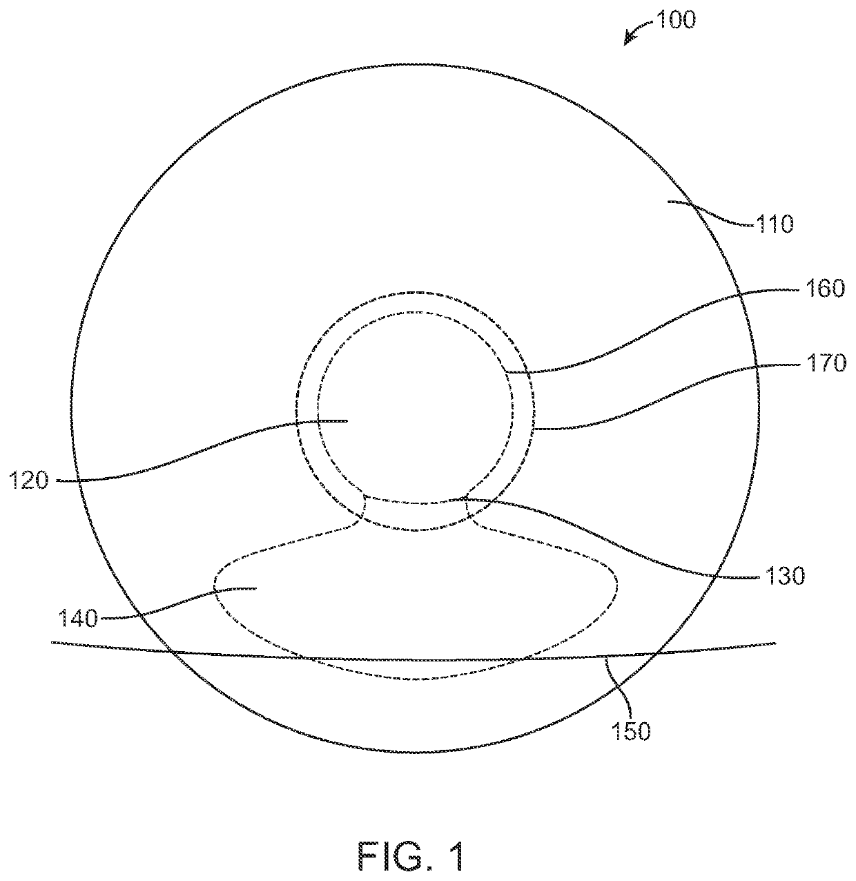
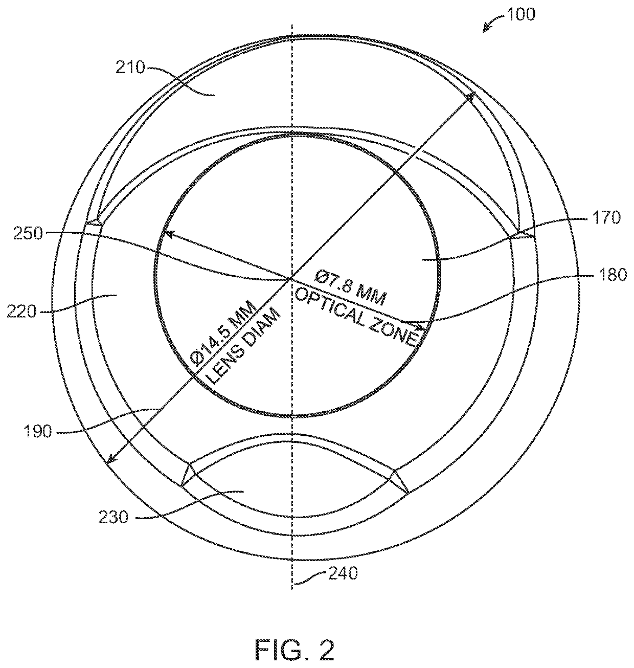
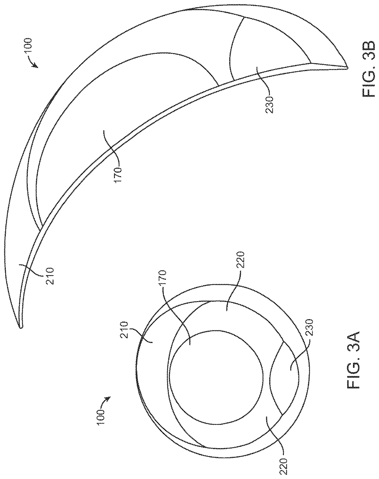
[0042]The contact lens and related methods and apparatus are well suited for many types of contact lenses, such as accommodating soft contact lenses. Although specific reference is made to stabilized accommodating contact lenses with fluidic coupling, the stabilized contact lenses disclosed herein can be used with many types of contact lenses, rigid and soft contact lenses and accommodating contact lenses such as electronic contact lenses, accommodating electronic contact lenses, other types of accommodating contact lenses response to engagement with a lower eyelid. The fluidic contact lens comprises an inner optical chamber configured to increase optical power and a lower chamber fluidically coupled to the optical chamber to increase optical power when the lower chamber engages the lower eyelid. The inner optical chamber and the lower chamber can be coupled to each other with a channel such as a microchannel.

[0043]As used herein the term “lower” refers to inferior on the subject wh...


PUM

PropertyMeasurementUnit
thicknessaaaaaaaaaa
thicknessaaaaaaaaaa
thicknessaaaaaaaaaa

Abstract

The stabilized contact lens methods and apparatus disclosed herein provide improved stabilization of a contact lens placed on a cornea of an eye. The contact lens comprises stabilization zones that allow the lens to repeatedly and consistently orient on the cornea such that a sensing zone located on the lower portion of the lens is located inferiorly to engage the lower eyelid. The stabilized contact lens can provide a lower pressure sensing zone with decreased thickness for pressure or other sensing related to the lower eyelid. The decreased thickness has the advantage of improving coupling between forces from an eyelid and a lower chamber of a fluidic module. The improved coupling allows increased amounts of fluid to move between the lower chamber and an upper optical chamber coupled to the lower chamber, such that the upper chamber can increase curvature and optical power in response to pressures of the eyelid.

Description

CROSS-REFERENCE[0001]This application is a continuation of PCT Application PCT / US2016 / 061697, filed Nov. 11, 2016, entitled “ROTATIONALLY STABILIZED CONTACT LENS”, which claims the benefit of U.S. Provisional Application Nos. 62 / 255,242, filed Nov. 13, 2015, entitled “ROTATIONALLY STABILIZED CONTACT LENS”, and 62 / 254,080, filed Nov. 11, 2015, entitled “ROTATIONALLY STABILIZED CONTACT LENS”, which applications are incorporated herein by reference.[0002]The subject matter of the present application is related to the following patent applications: PCT / US2014 / 013427, filed on Jan. 28, 2014, entitled “Accommodating Soft Contact Lens”; PCT / US2014 / 013859, filed on Jan. 30, 2014, entitled “Manufacturing Process of an Accommodating Contact Lens”; PCT / US2014 / 071988, filed on Dec. 22, 2014, entitled “Fluidic Module For Accommodating Soft Contact Lens”; U.S. Application Ser. No. 62 / 031,324, filed Jul. 31, 2014, entitled “Sacrificial Molding Process for an Accommodating Contact Lens”; PCT / US2015...

Claims


Application Information

Patent Timeline
Patent Type & Authority Patents(United States)
IPC IPC(8): G02C7/04G02C7/06G02C7/08G02C7/02B29D11/00
CPCG02C7/048G02C7/028G02C7/083G02C7/085B29D11/00028
Inventor PAYOR, RICKGOBRON, STEPHANELUBBERMAN, BENWAITE, STEVE
Owner ONEFOCUS VISION
Why Eureka
Try Eureka